ADM-
XP
User Manual
ADM-XR-IIPro User Manual
Page 9 of 29
Version 0.2
4 Local Bus Architecture
The XP implements a multi-master local bus between the bridge and the target FPGA using a 32 or 64
multiplexed address and data path. The bridge design is asynchronous and allows the local bus to be run
faster or slower than the PCI bus clock to suit the complexity of the user design.
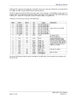
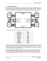
4.1 Local Bus signals
2V1500 PCI
to
Local Bus Bridge
PCI BUS
Target FPGA
2VP70/2VP100
Bank 3
lad[0:63]
lbterm_l
lbe_l[0:7]
lads_l
lblast_l
lready_l
ldreq_l[1:0]
lreset_l
lwrite
ldack_l[1:0]
fhold
fholda
Signalling Virtex2Pro
default - 2.5V (fast)
LVCMOS/LVTTL
lclk
AT21
AF1
AF2
AG12
AF7
AD10
AD9
AC10
AC9
Signal Type
Purpose
lad[0:63]
bidir Address and data bus.
lreset_l
unidir Reset to target
lads_l
bidir Indicates address phase
lblast_l
bidir Indicates last word
lbterm_l
bidir Indicates ready and requests new address phase
lready_l
bidir Indicates that target accepts or presents new data
lclk
unidir Clock to synchronise bridge and target
lbe_l[0:7] bidir Byte
qualifiers
dreq_l[0:1] unidir DMA request from target to bridge
dack_l[0:1] unidir DMA acknowledge from bridge to target
fhold unidir
Target
bus
request
fholda
unidir Bridge bus acknowledge
4.2 Local Bus Transfers
Please refer to the ADM-XRC SDK Help for Windows supplied with the XP for information on local bus
transfers.


