ADM-
XP
User Manual
ADM-XR-IIPro User Manual
Page 24 of 29
Version 0.2
10 User I/O XRM IO146 Front Panel Variant – Rev2.0
There are 146 I/O signals available on the front panel connector and these can be used individually or in pairs.
All of these pins are compatible with 2.5V and 3.3V signaling (dependant on IO voltage setting on JP1). Care
must be taken when using these signal pins not to exceed the maximum ratings for the V2PRO device.
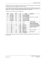
Each pair of I/O signals is routed as shown below.
FPGA IO
CON
Rs
Rs
Rs
Rs
Rt
Rt
User[0]
User[1]
User[2]
User[3]
The default manufacturing option is Rs=0R and Rt not fitted. Other options are available. Rs can be used to
provide series damping in point to point applications but for LVDS is 0R. Rt is required for LVDS inputs to
provide the termination voltage from the line current.
Pin numbering looking into front of XRM IO146 connector
2
152
151
1


