ADM-
XP
User Manual
ADM-XR-IIPro User Manual
Page 12 of 29
Version 0.2
5.3 SDRAM DDR Memory
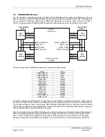
The XP provides 2 independent banks of 64MB of DDR SDRAM with the option of 128MB when devices
become available. Two Micron MT46V16M16 devices are fitted and are organised as 4Mx16x4. These devices
can be operated at between 75MHz and 133MHz and depending on resource usage within the FPGA, a
2VP70 can easily achieve 100MHz (DDR200) operation. Both banks are driven from Bank2 of the V2Pro.
2VP70 / 2VP100
FF1704
DQ1[16:31]
DDR1_CLK
DDR1_CLKB
DQS1[2:3]
DQM1[2:3]
DQ1[0:15]
DQS1[0:1]
DQM1[0:1]
DDR1_AD/BA/CTL
DDR1_CLK_FB
Bank 2
VCCO=2.5V
DDR
SDRAM
DQ0[16:31]
DQS0[2:3]
DQM0[2:3]
DQ0[0:15]
DQS0[0:1]
DQM0[0:1]
DDR SDRAM
Bank 0
DDR SDRAM
Bank 1
DDR
SDRAM
DDR
SDRAM
DDR
SDRAM
DDR0_AD/BA/CTL
DDR0_CLK_FB
DDR0_CLK
DDR0_CLKB
The pins required for the SDRAM controller for each bank are listed below.
The DDR controller uses SSTL1 IOB’s for data and control and SSTL1 for address and clocks - Please refer to
the UCF for locations of the DDR pins. Please note that the FPGA requires the Vref pins to be connected for
correct data reception on bank 3 when using SSTL standard. Additionally, bank 4 Vref pins connect to board
Vref but are not required for user applications. These pins should not be configured with pull-up or pull-down
options otherwise the Vref level will be set incorrectly.
The XP is designed to support DDR interface cores supplied by Xilinx using 90 degree phase shifted clocks for
DQS during write operations. This requires DQS pins occupy IOB’s that do not share a clock signal with DQ
pins. In the XP, DQS[0:1] and DQS[2:3] occupy pairs of IOB’s sharing a common clock. Note A trace delay
has been incorporated on the DQS lines of approx 1.5ns to allow the use of local clocking within the FPGA
Name Type
DDR_ad[0:12] Output
DDR_dq[0:31] Bidir
DDR_dqs[0:3] Bidir
DDR_rasb Output
DDR_casb Output
DDR_web Output
DDR_ba[0:1] Output
DDR_clk Output
DDR_clkb Output
DDR_csb Output
DDR_cke Output
DDR_dm[0:1] Output
DDR_clk_fb Input


