ADM-
XP
User Manual
ADM-XR-IIPro User Manual
Page 22 of 29
Version 0.2
9.5 Input
and
Output
Assignments (ADM-XP)
9.5.1 Mictor
I/O
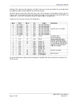
FPGA XRM-ETH
Bank Pin Samtec
J2
Mictor
Signal
1 E10 3 1
PAIR_1_P
1 D10 1 3
PAIR_1_N
1 D13 4 2
PAIR_2_P
1 C13 2 4
PAIR_2_N
1 E11 7 5
PAIR_3_P
1 F11 5 7
PAIR_3_N
1 H13 6 6
PAIR_4_P
1 G13 8 8
PAIR_4_N
1 H10 11 9
PAIR_5_P
1 J10 9 11
PAIR_5_N
1 L19 12 10
PAIR_6_P
1 M19 10 12
PAIR_6_N
1 F10 15 13
PAIR_7_P
1 G10 13 15
PAIR_7_N
1 K18 16 14
PAIR_8_P
1 L18 14 16
PAIR_8_N
1 C20 63 17
PAIR_9_P
1 D20 61 19
PAIR_9_N
1 F9 24 18
PAIR_10_P
1 E9 22 20
PAIR_10_N
1 L17 67 21
PAIR_11_P
1 K17 65 23
PAIR_11_N
1 C11 30 22
PAIR_12_P
1 C10 32 24
PAIR_12_N
1 J19 83 25
PAIR_13_P
1 K19 81 27
PAIR_13_N
1 G12 36 26
PAIR_14_P
1 F12 34 28
PAIR_14_N
1 G19 87 29
PAIR_15_P
1 H19 85 31
PAIR_15_N
1 M18 88 30
PAIR_16_P
1 M17 86 32
PAIR_16_N
1 K21 89 33
CLK2
1 J21 91 35
CLK3
1 F21 38 34
CLK0
1 G21 40 36 CLK1
1 F19 95 37
SINGLE_37
1 E19 93 38
SINGLE_38
9.5.2 DCI
Terminations
These pins should be prohibited for place and route. These pins have no other purpose on the XRM-ETH.
FPGA XRM-ETH
Bank Pin Samtec
Value
Signal
0 G27 103 100
VRN_0
0 H27 101 100
VRP_0
1 G9 17 100
VRN_1
1 H9 19 100
VRP_1


