ADM-
XP
User Manual
ADM-XR-IIPro User Manual
Page 8 of 29
Version 0.2
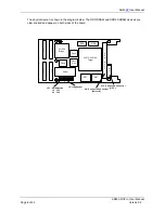
The physical layout is shown in the diagram below. The DDR DRAM and DDR2 SSRAM devices are
clam shelled and appear on both sides of the board.
J5 - Jtag Header
J
1
X
R
M
M
E
Z
Z
J
2
J
4
JP1 - VIO Selection
J
3
2V1500
Bridge
2VP70-2VP100
Target
ZBT
ZBT
1
Flash
DDR
DDR
Flash
M
G
T
Power
Clock
Gen
1
1
1-2 3.3V
2-3 2.5V
U8 - Samtec 180 Connector
(Select IO)
U13 - Samtec DP Connector
MGT's


