ADM-PCIE-8V3 User Manual
2.3 Thermal Performance
The ADM-PCIE-8V3 comes with a heat sink to reduce the heat of the FPGA which is typically the hottest point on
the card. The FPGA die temperature must remain under 100 degrees Celsius or the system monitor will clear the
FPGA design to ensure the card does not overheat. To calculate the FPGA die temperature, take your application
power and multiply by Theta JA from the chart below, and add your systems internal ambient temperature. If you
are using the fan provided with the board, you will find Theta JA is approximately 1.27 degC/W for the board in
still air.
The power dissipation can be estimated by using the Alpha Data power estimator in conjuction with the Xilinx
Power Estimator (XPE) downloadable at http://www.xilinx.com/products/technology/power/xpe.html. Download
the UltraScale tool and set the Device to Virtex UltraScale, VU095, FFVC1516, -2, Extended. Set the ambient
temperature to your system ambient and select User Override for the Effective Theta JA and enter the figure
associated with your system LFM in the blank field. Proceed to enter all applicable design elements and
utilization in the following spreadsheet tabs. Next aquire the 8V3 power estimator from Alpha Data by contacting
[email protected]. You will then plug in the FPGA power figures along with DDR4 and QSFP/Firefly
usage to get an estimated board level power dissipation.
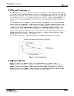
The graph below shows Theta JA of the board with two 3.5 watt QSFP loopback connectors inserted.
Figure 2 : Thermal Performance
2.4 Optional Blower
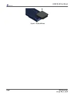
Because it is possible for generic PC chassis to not provide sufficient airflow to cool the FPGA, the
ADM-PCIE-8V3 is shipped with an uninstalled blower. The blower is optional and can be easily installed with a
Philips screw driver at the discretion of the user. Ensure the opening is facing the heatsink fins. The blower
hangs off the back of the PCB outside of the PCIe card envelope. After screwing the blower into the heatsink,
plug in the small power connector into the connector in the corner of the board.
Page 3
PCB Information
ad-ug-1308_v1_9.pdf


