ADM-PCIE-8V3 User Manual
3.2 Clocking
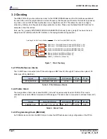
The ADM-PCIE-8V3 provides reference clocks for the DDR4 SDRAM banks and the I/O interfaces available to
the user. After a clock is programmed to a certain frequency, that frequency will become the default on power-up.
Any clock out of an Si5338 Clock Synthesizer is re-configurable over I2C. This allows the user to configure
almost any arbitrary clock frequencies during application run time. Please see the Alpha Data API functions for
examples of how this is done.
Note: use "set_property BITSTREAM.CONFIG.UNUSEDPIN {Pullnone} [current_design]" to ensure the user
design does not interfere with the I2C interface to the reprogramable clock generator.
NB6L11S
Fanout
QSFP28 161.1328125MHz Factory Default (MGTREFCLK0_129)
QSFP28 161.1328125MHz Factory Default (MGTREFCLK0_128)
FABRIC_CLK 300MHz (IO Bank 94)
PCIe Ref Clock (MGTREFCLK0_226)
Card Edge PCIe Ref Clock (100MHz)
25MHz
30ppm
Source
Si5338
Clock
Synth
NB6L11S
Fanout
FireFly 161.1328125MHz Factory Default (MGTREFCLK0_126)
FireFly 161.1328125MHz Factory Default (MGTREFCLK0_125)
NB6L11S
Fanout
Memory Interface Clock 300Mhz (IO Bank 44)
Memory Interface Clock 300Mhz (IO Bank 94)
Figure 7 : Clock Topology
3.2.1 PCIe Reference Clocks
The 16 MGT lanes connected to the PCIe card edge use MGT tiles 224 through 227 and use the system 100
MHz clock (PCIE_REFCLK).
Signal
Target FPGA Input
I/O Standard
"P" pin
"N" pin
PCIE_REFCLK
MGTREFCLK0_226
HCSL
AA7
AA6
Table 5 : PCIe Reference Clocks
3.2.2 Fabric Clock
The design offers a fabric clock called FABRIC_CLK which is permanently fixed at 300 MHz. This clock is
intended to be used for IDELAY elements in FPGA designs. The fabric clock is connected to a Global Clock (GC)
pin.
Signal
Target FPGA Input
I/O Standard
"P" pin
"N" pin
FABRIC_CLK
IO_L12P_T1U_GC_94
DIFF_HSTL_I_18
AP26
AP27
Table 6 : Fabric Clock
3.2.3 Programming Clock (EMCCLK)
An 100MHz clock is fed into the EMCCLK pin to drive the BPI flash device during configuration of the FPGA.
Page 8
Functional Description
ad-ug-1308_v1_9.pdf


