


Allied Construction Products, LLC www.alliedcp.com
TM103349_SP1000B_15sep
22
12.0 Technical Information – [cont'd]
Operating Pressure
– A measure of the hydraulic oil
pressure (values given in PSI / BAR) taken in the
attachment’s supply line during operation.
Oil pressure will fluctuate with changes to soil density
and the force exerted on the rubber springs by the
carrier. With the Skid-Pac raised off the ground, the
oil pressure is minimal. Each component of the
hydraulic system has a maximum working pressure.
For safety and reliability, it's important to regulate
pressure so that no component is subjected to
pressures beyond their design.
IMPORTANT
The operating pressure is not to be used as a
relief valve pressure setting. Poor performance
and significant heat generation will occur.
Relief Valve
– An adjustable, spring-loaded valve
that opens when a preset pressure value is reached.
A relief valve is safety device, used to protect the
circuit against hydraulic overload. Relief valves vary
in design. Pilot controlled pressure relief valves are
designed so that the relief pressure increases very
little as the flow through the valve increases. For
Skid-Pac applications, they are recommended over
direct acting type relief valves.
CAUTION
The relief valve is a safety device, used to protect
the circuit against hydraulic overload. It is a
required component.
Fig. 12-1 Flow-Pressure Diagram
Dynamic Relief Pressure –
Also referred to as
“Cracking Pressure”. The pressure measured at the
moment the oil pressure exceeds the preset value of
the relief valve and the spool “cracks” open.
Static Relief Pressure
– Also referred to as “Full
Relief Pressure”. The pressure measured at the
moment the relief valve has opened fully and all oil is
by-passed.
Opening Curve
– The dynamic pressure is always
less than the static pressure. A relief valve adjusted
to a dynamic pressure of 3000 psi (200 Bar) will
crack open when the preset point is reached, but fully
opens at a higher pressure. The opening curve is the
rise of pressure between dynamic and static.
IMPORTANT
The carrier's hydraulic system must be capable of
providing the accepted oil flow at a pressure
equal to at least the dynamic relief pressure.
12.5 Hydraulic Motor Options
Multiple size motors are offered for the Skid-Pac to
ensure a close match with the carrier’s auxiliary
hydraulics. The primary consideration in selecting the
optimal size motor will be the oil flow. The rotation
speed of the motor must be kept inside a narrow flow
range. Verify hydraulic flow for proper motor selection
and valve set up. Refer to the Technical Data Table
for available motor options.
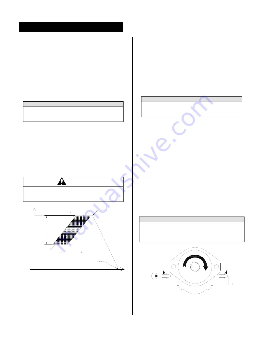
12.5.1 Motor Rotation
Refer to Fig. 12-2. The motor is assembled for
CLOCKWISE ROTATION. Motor ports are marked
[IN] and [OUT]. When viewed from the shaft end and
with the larger portion of the body downward, the [IN]
port is located on the left-hand side.
IMPORTANT
The motor is assembled for clockwise rotation.
Pressurizing the outlet port of the motor will damage
internal components. Verify correct installation
before pressurizing the hydraulic circuit.
Fig. 12-2 Motor Rotation Identified *Viewed From
Shaft End
FLOW
PRESSURE
Hydraulic
Flow Range
Operating
Pressure
Range
Static Relief Pressure
(No flow to attachment)
Dynamic Relief Pressure
(Relief valve cracks open)
Attachment
Operational
Range
Operating Pressure
Opening
Curve
IN
OUT
Summary of Contents for Skid-Pac 1000
Page 43: ...TM103349_SP1000B_15sep Notes ...
Page 44: ...TM103349_SP1000B_15sep R ...