background image

D620I_SVG

Figure 23

9.

Reinstall four hinge attaching screws, removed in Step 1.

D623I_SVG

Figure 24

 Wipe Out Inside of Dryer

Before using dryer for the first time, use an all-purpose clean-
er, or a detergent and water solution, and a damp cloth to re-
move shipping dust from inside dryer drum.

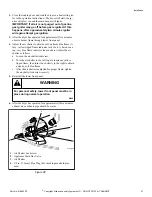
D618I_SVG

Figure 25

 Plug In the Dryer

 Electric Dryer

Connect the dryer to an electrical power source. Refer to 

Electric

Dryer Only - Connect Electrical Plug

 for information on con-

necting power cord.

Connect to 30 Amp circuit.

D275I_SVG2

Figure 26

 Gas Dryers

Dryer requires 120 Volt, 60 Hertz electrical supply and comes
equipped with a 3-prong grounding plug. Refer to serial plate for
specific electrical requirements.

NOTE: The wiring diagram is located in the control
hood.

WARNING

To reduce the risk of fire, electric shock, serious in-
jury or death, all wiring and grounding MUST con-
form with the latest edition of the National Electrical
Code, ANSI/NFPA 70, or the Canadian Electrical
Code, CSA C22.1, and such local regulations as
might apply. It is the customer’s responsibility to
have the wiring and fuses installed by a qualified
electrician to make sure adequate electrical power is
available to the dryer.

W521

When plugging in the dryer:

• Do not overload circuits.
• Do not use an adapter.
• Do not use an extension cord.
• Do not operate both a washer and gas dryer on the same cir-

cuit. Use separately fused 15 amp circuits.

The dryer is designed to be operated on a separate branch, polar-
ized, three-wire, effectively grounded, 120 Volt, 60 Hertz, AC
(alternating current) circuit protected by a 15 Ampere fuse,
equivalent fusetron or circuit breaker.

The three-prong grounding plug on the power cord should be
plugged directly into a polarized three-slot effectively grounded
receptacle rated 120 Volts AC (alternating current) 15 Amps. Re-
fer to 

Figure 27 

to determine correct polarity of the wall recepta-

cle.

Installation

  Part No. 510963R7

©

 Copyright, Alliance Laundry Systems LLC - DO NOT COPY or TRANSMIT

  19

Summary of Contents for Dryers

Page 1: ...Instructions for Dryers Original Instructions Keep These Instructions for Future Reference If this machine changes ownership this manual must accompany machine www alliancelaundry com Part No 510963R7 November 2014 ...

Page 2: ......

Page 3: ...uctions and local codes DO NOT install a clothes dryer with flexible plas tic venting materials If flexible metal foil type duct is installed it must be of a specific type identified by the appliance manufacturer as suita ble for use with clothes dryers Refer to section on connecting exhaust system Flexible venting materials are known to collapse be easily crush ed and trap lint These conditions w...

Page 4: ...g 14 Connecting Power Cord with Four Wire Plug 16 Reverse Door if Desired 17 Wipe Out Inside of Dryer 19 Plug In the Dryer 19 Electric Dryer 19 Gas Dryers 19 Grounding Information 20 Recheck Steps 20 Check Heat Source 20 Electric Dryers 20 Gas Dryers 20 Installer Checklist 22 Copyright 2014 Alliance Laundry Systems LLC All rights reserved No part of the contents of this book may be reproduced or t...

Page 5: ...mm E 43 in 1092 mm F 15 4 in 391 mm G 15 44 in 392 mm H 26 9 in 683 mm I 4 0 in 102 mm J 0 4 in 11 mm K 4 5 in 114 mm L 28 in 711 mm M 23 5 in 597 mm NOTE Exhaust openings are 4 inch 102 mm metal ducting With leveling legs turned into base Dimensions Part No 510963R7 Copyright Alliance Laundry Systems LLC DO NOT COPY or TRANSMIT 5 ...

Page 6: ...43 in 1092 mm F 15 4 in 391 mm G 15 44 in 392 mm H 2 8 in 70 mm I 2 3 in 60 mm J 26 9 in 683 mm K 4 in 102 mm L 0 4 in 11 mm M 4 5 in 114 mm N 28 in 711 mm O 23 5 in 597 mm NOTE Exhaust openings are 4 inch 102 mm metal ducting With leveling legs turned into base Dimensions 6 Copyright Alliance Laundry Systems LLC DO NOT COPY or TRANSMIT Part No 510963R7 ...

Page 7: ...Select a location with a solid floor Dryers installed in resi dential garages must be elevated 18 inches 457 mm above the floor No other fuel burning appliance should be installed in the same closet with the dryer The dryer must not be installed or stored in an area where it will be exposed to water and or weather Leveling legs can be adjusted from inside the dryer with 1 4 in driver All four legs...

Page 8: ...t Door DRY2664N_SVG 1 C A D E H 3 Front View Closet Door DRY2637N_SVG F F 2 G 1 Closet Door 2 Centered Air Openings G 2 Openings minimum 3 Outer Wall of Enclosure Figure 3 Installation 8 Copyright Alliance Laundry Systems LLC DO NOT COPY or TRANSMIT Part No 510963R7 ...

Page 9: ... IMPORTANT In mobile home installations gas dryers MUST be permanently attached to the floor at the time of installation Order No 526P3 Dryer Installation Kit available at extra cost for a manufactured mobile home installation Follow the instructions supplied with the kit Connect Dryer Exhaust System WARNING To reduce the risk of fire and the accumulation of combustion gases DO NOT exhaust dryer a...

Page 10: ...iltration rates should be equipped with an air exchanger that can accommo date on demand make up air needs in the laundry room These devices can be obtained through your building contractor or building material suppliers Static pressure in exhaust duct should not be greater than 0 6 inches water column 1 5 cm water column measured with manometer placed on exhaust duct two feet 610 mm from dryer ch...

Page 11: ... 8 m 1 55 feet 16 8 m 47 feet 14 3 m 2 47 feet 14 3 m 41 feet 12 5 m 3 36 feet 11 0 m 30 feet 9 1 m 4 28 feet 8 5 m 22 feet 6 7 m Table 2 NOTE Deduct 6 feet 1 8 m for each additional elbow NOTE The maximum length of a 4 in 102 mm diame ter flexible metal duct must not exceed 7 87 ft 2 4 m as required to meet UL2158 clause 7 3 2 A Installation Part No 510963R7 Copyright Alliance Laundry Systems LLC...

Page 12: ...in the ab sence of local codes and ordinances with the latest edition of the National Fuel Gas Code ANSI Z223 1 NFPA 54 or the CAN CSA B149 1 Natural Gas and Propane Installation Code Natural Gas 1000 Btu ft3 37 3 MJ m3 service must be supplied at minimum 5 0 inch 127 mm water column pressure to maxi mum 10 5 inch 267 mm water column pressure For proper operation at altitudes above 3000 feet 915 m...

Page 13: ...000 2440 56 0 0465 1 18 503786 Table 4 Connect Electrical Plug Electric Dryer Only Dryer requires 120 240 Volt or 120 208 Volt 60 Hertz 3 wire electrical supply Refer to serial plate for specific electrical re quirements IMPORTANT Use only a new U L listed No 0 copper wire only three conductor power supply cord kit rated 240 Volts minimum 30 Amperes and labeled as suita ble for use in a clothes dr...

Page 14: ...d dryer terminal block IS NOT supplied with dryer Type of power cord and gauge of wire must conform to local codes Connecting Power Cord with Three Wire Plug NOTE Four wire cord is required for new branch cir cuit installations mobile homes or where codes do not permit grounding through neutral NOTE The power cord is NOT supplied with the elec tric dryer Type of power cord and gauge of wire must c...

Page 15: ...vice Entrance Switch Box Refer to NOTE above 8 30 Ampere Fuses or Circuit Breaker 9 Neutral Wire 10 Metallic or Non Metallic Sheathed Cable Copper Wire Only 11 Power Cord Not supplied with dryer 12 Neutral 13 Terminal Block in Dryer 14 Intermediate Shut Off Box may or may not be fused 15 Direct Connection 16 Power Cord Connection Figure 6 1 Disconnect power to dryer 2 Remove access cover from rear...

Page 16: ... earth ground pin of the plug and the green screw on the back of the cabinet 8 Reinstall access cover and screw Connecting Power Cord with Four Wire Plug NOTE Four wire cord is required for new branch cir cuit installations mobile homes or where codes do not permit grounding through neutral DRY2016N_SVG 7 7 7 7 6 3 2 1 4 5 1 Typical Four Wire Receptacle 2 Power Cord Not Supplied with Dryer 3 Strai...

Page 17: ...Neutral terminal NOTE When installing the white wire loop the free eyelet end of the earth ground to neutral wire re moved in Step 4 and attach along with the white wire to the neutral center terminal on the terminal block 8 Tighten all screws firmly IMPORTANT Failure to tighten these screws firmly may result in wire failure at the terminal block 9 Check the continuity of the ground connection bef...

Page 18: ...e door strike from door liner and reinstall on opposite side DRY1917N_SVG Figure 20 6 Insert liner under flange on bottom of door then push top of door liner into place DRY1918N_SVG B A Figure 21 7 Reinstall nine screws removed in Step 2 DRY1919N_SVG Figure 22 8 Using screwdriver remove two door plugs and reinstall on opposite side of door opening Installation 18 Copyright Alliance Laundry Systems...

Page 19: ...t edition of the National Electrical Code ANSI NFPA 70 or the Canadian Electrical Code CSA C22 1 and such local regulations as might apply It is the customer s responsibility to have the wiring and fuses installed by a qualified electrician to make sure adequate electrical power is available to the dryer W521 When plugging in the dryer Do not overload circuits Do not use an adapter Do not use an e...

Page 20: ...e outlet have a proper outlet installed by a qualified electrician NOTE Have a qualified electrician check the polarity of the wall receptacle If a voltage reading is measured other than that listed on the dryer s nameplate the qualified electrician should correct the problem Do not operate other appliances on the same circuit when this ap pliance is operating WARNING To reduce the risk of an elec...

Page 21: ...me indicates too much air Adjust the air shutter as follows a Loosen the air shutter lockscrew b Turn the air shutter to the left to get a luminous yellow tipped flame then turn it back slowly to the right to obtain a steady soft blue flame c After the air shutter is adjusted for proper flame tighten the air shutter lockscrew securely 5 Reinstall the lower front panel WARNING For personal safety l...

Page 22: ...c D275I_SVG1 Gas D254I_SVG CHECK CHECK 3 GAS ONLY Connect Gas Sup ply Pipe Check for Gas Leaks D258I_SVG1 8 Recheck Steps CHECK CHECK 4 ELECTRIC ONLY Connect Electrical Cord D699I_SVG1 9 Check Heat Source D702I_SVG1 CHECK CHECK 5 Reverse Door if De sired D675I_SVG1 CHECK Refer to the manual for more detailed information Installer Checklist Part No 510963R7 Copyright Alliance Laundry Systems LLC DO...

Reviews: