


Rockwell Automation Publication 2715-UM001A-EN-P - July 2015
79
Install and Replace Components
Chapter 5
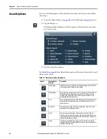
To replace the battery, follow these steps.
1.
Disconnect power from the terminal.
2.
Loosen the screws that secure the logic module to the back of the display.
3.
Carefully lift the logic module away from the display module and turn over
to expose the circuit board.
4.
Locate the coin-cell battery on the circuit board.
5.
Remove the battery by lifting on the side of the battery.
6.
Insert the new battery with the positive (+) polarity up.
7.
Reattach the logic module by aligning the connector on the bottom of the
logic module with the connector on the back of the display module.
This equipment is sensitive to electrostatic discharge (ESD).
Follow ESD prevention guidelines when handling this equipment.
Logic Module
Display Module
Summary of Contents for 2715-15CA
Page 6: ...6 Rockwell Automation Publication 2715 UM001A EN P July 2015 Table of Contents Notes...
Page 16: ...16 Rockwell Automation Publication 2715 UM001A EN P July 2015 Chapter 1 Overview Notes...
Page 88: ...88 Rockwell Automation Publication 2715 UM001A EN P July 2015 Chapter 6 Update Firmware Notes...
Page 104: ...104 Rockwell Automation Publication 2715 UM001A EN P July 2015 Index...
Page 105: ......


