background image


GLD

 Touch Screen Reference V1.2 – Issue 1                               28


ALLEN

&

HEATH


6.


I/O Screen 


6.1


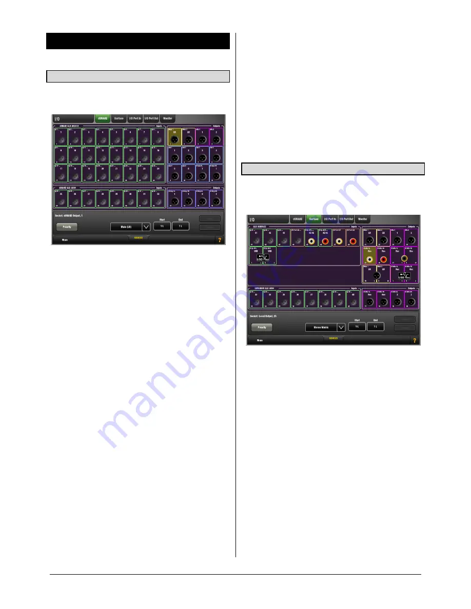
dSNAKE I/O page 

Patch Input and Output sockets on AudioRacks connected 
to the GLD via its dSNAKE port using this screen. 


AR2412

 Main AudioRack - 24 Mic/Line inputs and 12 XLR 

Line outputs. 

AR84

 Expander AudioRack connected to the AR2412 

EXPANDER Port – 8 Mic/Line inputs and 4 XLR Line 

outputs. 
The socket number and its assigned source or destination 
name and colour is displayed for each socket. 
 

SOURCES 

 pull-up window


An input socket could be assigned to multiple destinations, 
for example to one or more channels and the I/O Port. Use 
the pull-up to see a list of all destinations for a highlighted 
input socket. 
 

Note

  You can patch a single input socket to more than one 

channel or destination, but you can patch only one socket 
to a single channel or destination. 
 
Input sources can also be patched using the 

Preamp

 page 

for each channel. This method may be preferred. 

 
Patching Outputs

  -  Touch an output socket to highlight it. 

Use the lower part of the screen to select the GLD signal to 
assign to that socket. Open the menu to scroll through and 
select from the available sources. Choose the source 

number using the Start box and screen rotary. 
To assign a range of output sockets touch the End box and 
turn the screen rotary. The sockets about to be assigned 
are highlighted on the screen. 
Touch 

Apply

 to accept the assignment or 

Cancel

 to discard 

the change. 
 

Touch the 

Polarity

 button to reverse the polarity of a 

highlighted output socket. This affects the socket only, not 
the source assigned to it. 

 
Patching Inputs

  -  Touch an input socket to highlight it. 

Use the lower part of the screen to select the channel 
to assign the socket to. Choose the channel number using 
the Start box and screen rotary. 
To assign a range of input sockets touch the End box and 
turn the screen rotary. The sockets about to be assigned 

are highlighted on the screen. 
Touch 

Apply

 or 

Cancel

 to accept or discard the change. 


6.2


Surface I/O page 

Patch Input and Output sockets on the GLD surface and on 
an AudioRack connected via the surface Expander port 
using this screen. 


GLD rear panel sockets

 – XLR and RCA phono analogue 

I/O, and SPDIF and AES digital outputs. 

GLD top panel USB

 – Patching for stereo audio playback 

and recording. 

AR84

 AudioRack connected to the GLD surface 

EXPANDER Port – 8 Mic/Line inputs and 4 Line outputs. 
The socket number and its assigned source or destination 
name and colour is displayed for each socket. 
 
Assign output sockets from: 


Unassigned 


Input Direct Out 


Group 


Aux 


Main 


Matrix 


Rack FX 


USB playback 


Input socket 


I/O Port input 


PAFL monitor 


Wedge/IEM monitor 


Summary of Contents for DIGITAL MIXING SYSTEM

Page 1: ...DIGITAL MIXING SYSTEM Screen Reference Guide For GLD firmware Version V1 2 Check the Allen Heath web site for the latest version available Also read the GLD User Guide AP8561...

Page 2: ...e Manager page 31 7 2 Scene Recall Filter page 32 7 3 Cue List Editor page 33 7 4 Scene Safes page 34 8 Ganging Screen 35 9 Setup Screen Audio 36 9 1 PAFL Setup page 36 9 2 Talkback Setup page 36 9 3...

Page 3: ...a User Scene is set it is recalled automatically on login when the user is changed It does not recall when the same user logs in or when the system is powered up again while the same user is current...

Page 4: ...ectly may result in parameter changes made up to 30 seconds before power is removed becoming lost Lock Surface Touch the Lock Surface button and Yes in the confirmation popup to lock the surface contr...

Page 5: ...e master Master faders Channel faders Aux3 Aux3 Aux3 Sel Mix Sel Mix Preamp PEQ LF HPF GATE Routing LM HM HF Gain Normal mix mode FOH Master Mix Channel Mix Assign Routing Assign Routing Pre Post Sel...

Page 6: ...are stored in Show memories 3 2 Overview page Input Channel Input Channel processing pages are accessed by pressing an Input strip Sel key while the Processing screen is selected The Input Overview p...

Page 7: ...cted mix For a view of all Mix Channel delays open the Delay page Library The Mix Channel Library is accessed from the Overview page 3 4 Overview page FX Send or Return FX processing pages are accesse...

Page 8: ...call Preamp button setting is remembered when changing channels 3 6 Preamp page The Preamp page provides access to the Input Channel source patching socket Preamp settings and channel Trim and HPF Tou...

Page 9: ...PTIONS pull up window Provides a global setting for Preamp or Trim on Surface This affects all input channels Touch the pull up tab and swipe your finger upwards to open its window A note about Gain S...

Page 10: ...te on a rack tom to open In Switch the gate in or out of circuit The side chain can also be switched in or out of the gate The curve turns yellow and the gain reduction meter displays red when the gat...

Page 11: ...ands is available Sel button Touch while holding the Copy Paste or Reset key to copy the PEQ settings to other channels or to reset it flat 3 12 GEQ page A 28 band 1 3 octave Graphic Equaliser is prov...

Page 12: ...while in any of the mix Processing pages This puts the lower frequency half of the GEQ on to the faders Press again to present the higher frequency half and press again to return to normal fader mode...

Page 13: ...level Attack and Release These controls set how fast the compressor pulls back the signal when it exceeds the threshold and how long it takes to let go when the signal drops below the threshold Set t...

Page 14: ...en the Routing page for the currently selected Input Channel Touch the tabs within the page to access the assignments and send levels from the selected Input Channel to all Groups Auxes and FX its DCA...

Page 15: ...s are shown in the channel strip LCD displays For example with an Aux master selected Sends from all channels to the mix Sends from all FX returns to the mix Sends from all audio Groups to the mix Whi...

Page 16: ...this position Use the DCA Mute key as the Mute Group master DCA Groups explained A DCA group provides a master fader and mute to remotely control the level of channels assigned to it Audio does not ro...

Page 17: ...all meters in the Inputs page This does not affect the fader strip or other screen metering The following options are available all Pre Fader Post Trim Post Gate PEQ Post Compressor Post Delay Defaul...

Page 18: ...octave Real Time Analyser frequency display for the signal currently PAFL signal The RTA can be viewed in the Home or Meters screens It also displays on the strip meters when GEQ Fader Flip is active...

Page 19: ...then check that the related Send master and Return faders are turned up and that they are not muted or affected by a DCA Group PEQ Each FX Return has a 4 band Parametric Equaliser Touch the PEQ button...

Page 20: ...e SMR Reverb SMR Live is a Spatial Modelling Reverberator featuring 4 fully configurable complex spatial models Classic Hall Room and EMT Each of these models use different reflection and decay algori...

Page 21: ...ft and right delay can be dialled in using the screen Rotary tapped on screen or tapped using a SoftKey Individual tap indicators flash at the tap rate The left and right delay taps can be ganged to m...

Page 22: ...brary window ADT Doubler An Automatic Double Tracking module capable of creating short echo chorusing classic double tracking and slapback tape delay loops The ADT is very effective in creating stereo...

Page 23: ...n sine wave and rectified LFO modulator Autopan Automatically pans the chorus voices wet signal only not the dry signal This is level modulation of the wet effect not the dry signal across the stereo...

Page 24: ...n untameable dramatic effect The sound turns inside out Preset Name is displayed Touch and scroll using the screen Rotary for live update This is a way of live auditioning all library presets for this...

Page 25: ...both Left and Right signal paths and presented on one meter UPPER FREQ CUT Controls the upper bandwidth of the sub bass harmonic spectrum This setting depends greatly on the sub bass speaker equipmen...

Page 26: ...resets for this module factory user and USB You can also select and recall a particular preset using the Library window Rotator The Rotator is a model of a traditional rotary speaker cabinet such as t...

Page 27: ...results in both voices being set to zero Preset Name is displayed Touch and scroll using the screen Rotary for live update This is a way of live auditioning all library presets for this module factory...

Page 28: ...o assign a range of output sockets touch the End box and turn the screen rotary The sockets about to be assigned are highlighted on the screen Touch Apply to accept the assignment or Cancel to discard...

Page 29: ...box and turn the screen rotary The outputs about to be assigned are highlighted on the screen Touch Apply or Cancel to accept or discard the change Touch the Polarity button to reverse the polarity o...

Page 30: ...p to the MMO sockets as below GLD Port Map Port Out MMO ADAT 1 ADAT 1 2 ADAT 2 3 ADAT 3 4 ADAT 4 5 ADAT 5 6 ADAT 6 7 ADAT 7 8 ADAT 8 9 ADAT 9 10 ADAT 10 11 ADAT 11 12 ADAT 12 13 ADAT 13 14 ADAT 14 15...

Page 31: ...e you wish to copy Touch the Copy button Touch the Scene you wish to copy to Touch the Paste button to paste the contents and filter settings to that Scene Note Copying a Scene copies its contents and...

Page 32: ...Block All or Allow All button at bottom left Touch Close to return to the main Scene Manager view 5 4 3 2 1 Close Scene Recall Filter parameters For Inputs FX Returns FX mix Grp Aux Main Mtx Preamp G...

Page 33: ...ers in the list To remove Scenes from the Cue List Touch the trash can icon to the right of the Scene name This removes it from the Cue List but not the All Scenes list To clear all Scenes from the Cu...

Page 34: ...parameters for one channel Touch label on left 4 All items in the current tab Touch Toggle All Safes are applied immediately No confirmation is needed Safes settings are stored in Show memories 4 3 2...

Page 35: ...g the Routing attribute links the assignments and sends from the ganged channels Touch Apply or Cancel to accept or delete the changes Using Gangs Use the Gangs to suit the way you prefer to mix Some...

Page 36: ...tor mixing Mix follows Mix PAFL Pressing a Mix master strip PAFL key selects Mix for that master Mix follows Input PAFL Pressing an Input channel strip PAFL key selects Mix for that channel Sel follow...

Page 37: ...setting Note The Signal Generator is disabled while Talk is active 9 3 SigGen page The Signal Generator SigGen is a useful tool providing a steady test signal to help you align and test a live sound s...

Page 38: ...188KB sec Therefore allow 11 5MB per minute 700MB per hour Note Maximum recording time for one track 3 hours To assign a recording source Touch the Assign button to open the I O Surface screen to pat...

Page 39: ...r console is the Master and has control of the mic preamps in AudioRacks connected to it This console is set for Internal audio clock source FOH console This console is the Slave getting its mic input...

Page 40: ...up window Use the pull up to choose to sync the Layer shown on the screen with the currently selected surface Layer Select the Bank to work with The screen will follow the Layer currently selected on...

Page 41: ...stom MIDI message string Talkback Assign Talkback to different outputs Level Up Tap to increase level for faders Level Down Tap to decrease level for faders Send Level Up Tap to increase level for Aux...

Page 42: ...alternative information display on the fader strip LCD while it is held To choose an Alt View option Open the drop down menu and touch an item to select it Alt View display options The strip LCD norm...

Page 43: ...eset Shows are not cleared during a firmware update To Store a new Show Touch the Store Show button Type in a name using the keypad Touch Apply Touch OK in the popup to return to the Show list To over...

Page 44: ...r bank assigned with input channels 11 3 Library Manager page Use this page to edit and transfer User and USB Libraries Library memories include Channel Processing Preamp option Mix Processing PEQ GEQ...

Page 45: ...x with independent stereo LR and mono M buses Channels can be separately assigned to any combination of LR and M Typical application for M is main centre speaker mono PA or bus fed sub bass LCR A 3 wa...

Page 46: ...ed in The Admin user Administrator has access to all functions and can set permissions and allocate passwords if required for the other users Up to 9 other Users may be set up for example volunteer op...

Page 47: ...user at any time by going to the Home Users screen You can also change user at the Login screen when powering up the GLD if a password has been set If a password has been set then you are also prompte...

Page 48: ...ng the settings Changing these settings will automatically restart the touch screen 13 3 Calibration Setup page The Calibration Setup page lets you recalibrate the accuracy of the touch screen or moto...

Page 49: ...will not load on systems running earlier versions However earlier versions of Shows will load on GLD running later versions of firmware Features introduced on more recent firmware will not be recalle...

Page 50: ...a Show go to the Setup Memories Show Manager screen Loading a Template Show will Restore a default configuration and layout Reset user preferences Zero the board current settings Reset the processing...

Reviews: