© Allegion 2020
Printed in U.S.A.
P519-087 Rev. 01/20-b
Continue to User Guide
Scan the QR code
for online interactive
instructions, user guide,
warranty, and reference
information.
alle.co/nde
Factory Default Reset (FDR)
A Factory Default Reset (FDR) will return the NDEB lock
settings to the original settings as shipped from the factory.
Removes configurations, databases, and requires the lock
to be re-captured. A FDR will not remove the lock from your
ENGAGE account.
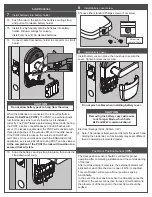
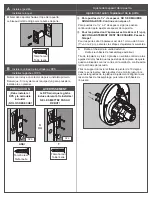
A
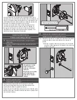
Press and hold the FDR button for five seconds.
The NDEB will blink green two times and beep two times.
B Turn the inside lever three times within 20 seconds.
LED will blink red and lock will beep with each turn.
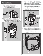
C Reinstall battery cover, then use the app to capture
your lock.
Turn the inside lever. The NDEB will communicate on BLE
looking for your mobile device for two minutes after each
lever turn in FDR mode.
If you have used this NDEB in Construction Access Mode,
you must complete a FDR before it will communicate on BLE.
FCC Statement
This equipment has been tested and found to comply with the limits for a Class B digital
device, pursuant to Part 15 of the FCC Rules. These limits are designed to provide
reasonable protection against harmful interference in a residential installation. This
equipment generates, uses, and can radiate radio frequency energy and, if not installed
and used in accordance with the instructions, may cause harmful interference to radio
communication. However, there is no guarantee that interference will not occur in a
particular installation. If this equipment does cause harmful interference to radio or
television reception, which can be determined by turning the equipment off and on, the
user is encouraged to try to correct the interference by one of the following measures:
Reorient or relocate the receiving antenna.
Increase the separation between the equipment and receiver.
Connect the equipment into an outlet on a circuit different from that to
which the receiver is connected.
Consult the dealer or an experienced radio/TV technician for help.
FCC Caution:
Any changes or modifications not expressly approved by the party
responsible for compliance could void the user’s authority to operate this equipment.
This device complies with Part 15 of the FCC Rules. Operation is subject to the following
two conditions: (1) This device may not cause harmful interference, and (2) this device
must accept any interference received, including interference that may cause undesired
operation.
FCC Radiation Exposure Statement
To comply with FCC/IC RF exposure requirements for mobile transmitting devices, this
transmitter should only be used or installed at locations where there is at least 20 cm
separation distance between the antenna and all persons.
Industry Canada Statement
Under Industry Canada regulations, this radio transmitter may only operate using an
antenna of a type and maximum (or lesser) gain approved for the transmitter by Industry
Canada. To reduce potential radio interference to other users, the antenna type and its
gain should be so chosen that the equivalent isotropically radiated power (e.i.r.p.) is not
more than that permitted for successful communication.
Industrie Canada Déclaration
Conformément à la réglementation d’Industrie Canada, le présent émetteur radio peut
fonctionner avec une antenne d’un type et d’un gain maximal (ou inférieur) approuvé
pour l’émetteur par Industrie Canada. Dans le but de réduire les risques de brouillage
radioélectrique à l’intention des autres utilisateurs, il faut choisir le type d’antenne et son
gain de sorte que la puissance isotrope rayonnée équivalente (p.i.r.e.) ne dépasse pas
l’intensité nécessaire à l’établissement d’une communication satisfaisante.
Industry Canada Radiation Exposure Statement
This Device complies with Industry Canada License-exempt RSS standard(s). Operation
is subject to the following two conditions: (1) this device may not cause interference,
and (2) this device must accept any interference, including interference that may cause
undesired operation of the device.
Industrie Canada l’exposition aux radiations
Le présent appareil est conforme aux CNR d’Industrie Canada applicables aux appareils
radio exempts de licence. L’exploitation est autorisée aux deux conditions
suivantes : (1) l’appareil ne doit pas produire de brouillage, et (2) l’appareil doit
accepter tout brouillage radioélectrique subi, même si le brouillage est susceptible d’en
compromettre le fonctionnement.
UL Statements
• Outside lever is normally locked. Inside lever always allows
egress.
• Unit shall not interfere with the operation of Panic Hardware.
•
Wireless communication, Wifi, door position, and request
to exit have not been evaluated by UL. Any Bluetooth
programming, remote control, or monitoring has not been
evaluated by UL. Bluetooth electronic credentials are
considered supplemental.
• The model NDEB has been tested to the following UL294
7th edition performance levels: Standby Power Level I,
Endurance Level IV, Line Security Level I, and Destructive
Attack Level I
• Tested to compliance with CSA-C22.2-M1983.
Customer Service
1-877-671-7011
www.allegion.com/us

