6
www.Observint.com
© 2015 Observint Technologies. All rights reserved.
fails), load balancing (LAN1 and LAN2 ports are connected to the same network, and bandwidth load balancing occurs between the
two LAN ports), or multi-address (where the LAN ports can function independently on different networks).
5.
Connect the power cord to the power connector on the back panel of the NVR, and then into a UPS (preferred) or surge protector.
NOTE
Do not power on the NVR at this time.
Installing an HDD in the NVR
If you purchased your NVR with pre-configured HDDs, each HDD is labeled for the drive bay they should be installed in. A diagram identifying
the drive bay locations is provided on the inside of the front cover.
If you purchased your NVR without an internal HDD(s), you install at least one for the NVR to function properly. the NVR will accommodate up
to 16 HDDs, each with a capacity of up to 4TB.
The HDDs are installed behind the front panel. To install HDDs, do the following:
1.
If necessary, unlock the front panel using the keys provided.
2.
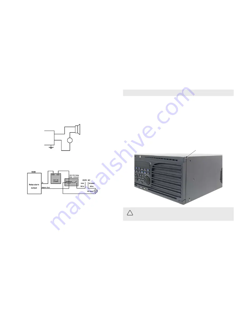
Simultaneously press the buttons at each end of the front panel to unlatch it, and then fold the panel down.
Front panel latch button
(one on each side)
CAUTION
Follow recommended electrostatic discharge (ESD) guidelines while performing this procedure. Install the HDD in a static-free
environment, wearing a certified ESD wrist strap. If a static free environment and ESD wrist strap is not available, touch the bare metal of
the recorder chassis frequently when installing the drive to dissipate the static charge naturally generated on your skin and clothing and
avoid touching electronic components.
3.
Unpackage an HDD, and then install disk mounting handles on each side as shown below. Use three screws (provided) to attach each
handle.
To remove a jumper for AC load alarm circuits:
1.
Disconnect all cabling from the NVR.
2.
Remove the NVR top cover.
3.
Locate the jumper associated with the alarm output you are using for an AC load alarm, then remove it. Save the jumper for use later,
if needed.
4.
Reinstall the NVR top cover.
DC load alarm output circuits
DC loads must operate within the limitation of 12V/1A. To connect to a DC alarm output, use the following diagram:
NVR
DC
OUT
Gnd
DC load
+
–
AC load alarm output circuits
To connect an AC load to an alarm output, a jumper, associated with the output on the alarm termination PC board, (within the chassis), must
be removed. These jumpers shunt pin pairs J1, J2, J3, and J4 for alarm outputs 1, 2, 3, 4 respectively. Use an external relay for safety.
Install a monitor, mouse, power
For the following steps, refer to the back panel photo above for the location of connectors.
1.
Install and setup your monitor in accordance with the instructions provided with the monitor. Do not power it on at this time.
2.
Cable the HDMI or VGA connector to your monitor’s VGA or HDMI input. The HDMI interface provides the best performance.
3.
Plug the mouse into the USB connector on the front or back of the NVR.
4.
Connect the LAN1 and LAN2 connectors to a ethernet network(s). Note that the NVR support two LAN ports that can be configured for
net fault-tolerant mode (LAN1 and LAN2 ports are connected to the same network, and a rollover to a spare port occurs when a port


