5
www.Observint.com
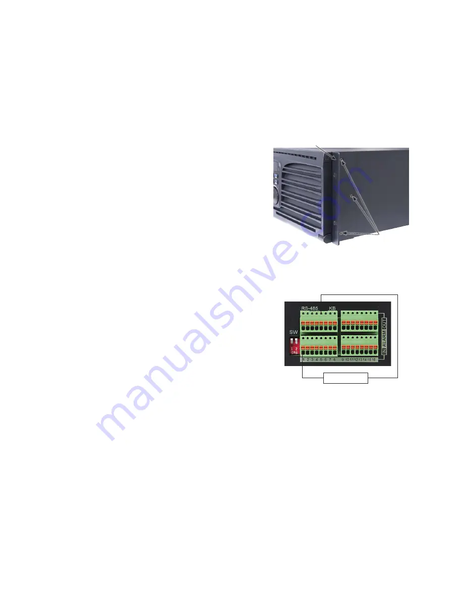
Rack mount bracket
Mounting screws (3)
Wiring alarm inputs to the NVR
You can wire up to 16 alarm inputs to the NVR. Alarm input wiring connects to the RS-485, Alarm IN/OUT connector blocks on the back of the
NVR.
Sensor
–
+
Typical ALARM IN wiring
Wiring alarm outputs to the NVR
The NVR provides 4 alarm output terminations. These terminations for each output are on the ALARM OUT connector block on the back of the
NVR , and are labeled 1 - G, 2 - G, 3 - G, 4 - G (G = ground termination).
There are 4 jumpers (JP1, JP2, JP3, and JP4) inside the chassis on the alarm termination PC board, associated with ALARM OUT pins 1, 2, 3
and 4 respectively. Initially, these jumpers are in place. If connecting an alarm output to a DC loaded alarm out circuit, the jumper must be in
place. If connecting the alarm output to an AC loaded alarm, the corresponding jumper must be removed. Example: If you connect an AC load
to the alarm output 3 of the NVR, then you must remove the JP 3.
NVR installation general guidelines:
NVR Placement
Your monitoring and recording equipment is the core device for constant surveillance and the reliable capture of video evidence. Observint
Technologies strongly suggest that it be installed in a secure location with access limited to authorized personnel. The NVR can be installed
on a shelf, or in a rack using the rack mounting brackets provided.
NVRs and monitors generate heat and should be placed in a clean and well ventilated area. A high temperature environment will reduce the
life span and reliability of the equipment. Additionally, the NVR is not weatherproof, so avoid exposure to liquids and excessive dust. Also, do
not place objects along the sides or behind the NVR that will block cooling airflow through the chassis or prevent access to the back panel
cabling.
Uninterruptible power supplies
It is strongly suggested that power to the system be routed through an uninterruptible power supply (UPS). These devices will keep your
security system running through most power outages, in addition to providing excellent surge and sag protection. The UPS should support
the NVR and all cameras to ensure normal operation during abnormal power conditions.
IP cameras monitored by the NVR
Your NVR connects to other devices through Ethernet networks. They must be accessible from the network(s) the NVR is connected to.
Ethernet network considerations
The NVR contains two network interfaces: LAN1 and LAN2, which can be configured in one of three modes:
•
Net Fault-tolerance Mode
: LAN1 and LAN2 are connected to the same network and use the same IP address but only one interface
(the one configured as Main) is active at any one time. If the main network interface failure, the device will automatically enable the
other (standby) network interface to ensure the normal operation of the system.
•
Load Balance Mode
: In this configuration, LAN1 and LAN2 are connected to the same network and have the same IP address. They
wile share the load of the total bandwidth, which enables the system to provide two gigabit network capacity.
•
Multi-address Mode
: The parameters of LAN1 and LAN2 can be configured independently and connected to different networks. You
can select LAN1 or LAN2 in the NIC type field for parameter settings. This configuration can be used in different ways. For instance,
you can use one network to stream all camera video/data to and from the cameras and the other network to monitor the NVR, or
access cameras on two networks and stream camera video/data from both to improve network bandwidth.
The NVR must be positioned within 100 meters (330 ft) to an ethernet network switch or hub.
Rack mounting the NVR
The NVR is provided with chassis rack mount brackets. If installing the NVR in a rack,install a bracket on each side of the NVR as shown below.
Secure a bracket to each side of the NVR using three screws (provided). The NVR requires 3 rack units of vertical space.
© 2015 Observint Technologies. All rights reserved.


