background image

53

ALI-NT4002R, ALI-NT2002R Cameras User Manual

SECTION 3 IMAGE SETTINGS

Example

: Select Area 2 and Area 3, and set the comparison rule as Above (Max. Temperature), Set the temperature difference 

threshold to 15 °F. The device will generate an alarm when the difference of two areas’ maximum temperature is above 15 °F.

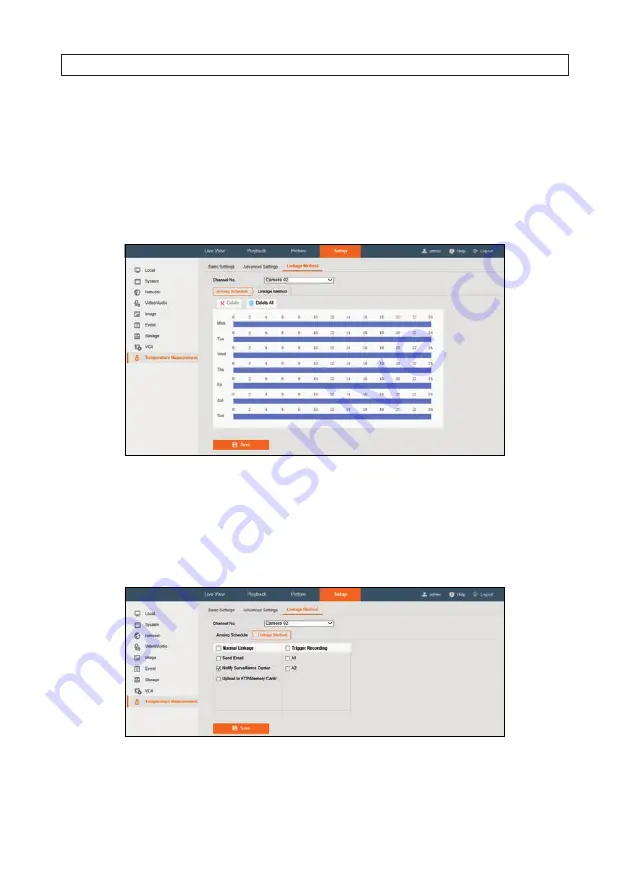
3.5.3  Linkage Method

Set the linkage method of the alarm.
1.  Open the Linkage Method menu. Go to: 

Setup | Temperature Measurement | Linkage Method

.

2.  Set the arming schedule and linkage method.

a. 

Arming Schedule 

(see above): Click on the time bar and drag the mouse to select the time period.

b. 

Linkage Method

: Click Linkage Method and check the select box to select the linkage method. Audible warning, notify 

surveillance center, send email, upload to FTP, trigger channel and trigger alarm output are selectable. You can specify the 
linkage method when an event occurs.

3.  Click 

Save

.

After the settings, you can view the current temperature and humidity on the top of this menu.

Summary of Contents for ALI-NT2002R

Page 1: ...Network Cameras User Manual ALI NT2002R camera ALI NT4002R camera PLEASE READ THIS MANUAL BEFORE USING YOUR CAMERAS and always follow the instructions for safety and proper use Save this manual for fu...

Page 2: ...ries Observint disclaims liability associated with the use of non Observint authorized accessories The recording transmission or broadcast of any person s voice without their consent or a court order...

Page 3: ...y cause undesired operation Preventive and Cautionary Tips Before connecting and operating your cameras please be advised of the following Ensure environmental conditions meet factory specifications M...

Page 4: ...r packing materials providing the same protection If the product does not work properly please contact your dealer or the nearest service center Never attempt to disassemble the camera yourself We sha...

Page 5: ...ion box 12 2 1 5 Connect extension cables to the camera drop cables 13 2 2 ALI NT2002R installation 15 2 2 1 What s in the box 15 2 2 2 Install a microSD card optional 15 2 2 3 Install the camera 17 2...

Page 6: ...ement Basic Settings 47 3 5 2 ConfiguringTemperature Measurement Rule 48 3 5 3 Linkage Method 53 3 5 4 ConfigureVCA Rule 54 SECTION 4 Event Setup 55 4 1 Basic Events 55 4 1 1 Configuring Motion Detect...

Page 7: ...tings 83 6 1 1 Capture 86 6 2 Storage Management 88 6 2 1 HDD Management 88 6 2 2 NetHDD 89 APPENDIX A Lightning and Surge Protection 91 APPENDIX B 24VacWire Gauge andTransmission Distance 92 APPENDIX...

Page 8: ...viii NOTES...

Page 9: ...mK 25 C F 1 1 Powerful behavior analysis function based on deep learning algorithm Line crossing Intrusion Region Entrance Exit Reliable temperature exception alarm function Advanced fire detection al...

Page 10: ...set microSD card slot addess on underside camera body Camera body Adjustable bracket Bracket lock screw Sun shield Junction box Conduit junction Optical camera lens ALI NT4002Rcamerawithjunctionbox 1...

Page 11: ...re Measurement 3 temperature measurement rule types 21 rules 10 points 10 areas and 1 line Temperature Range 4 F 302 F 20 C 150 C Temperature Accuracy 14 4 F 8 C Fire detection Dynamic fire point dete...

Page 12: ...Ethernet interface 1 RS 485 interface SD Memory Card Built in microSD card slot support microSD SDHC SDXC card up to 128 GB support manual alarm recording Analog Video Output 1 0 V p p 75 PAL NTSC BN...

Page 13: ...Plane Arrays Max Resolution 160 120 the resolution of output image is 320 240 Pixel Interval 17 m Response Waveband 8 m to 14 m NETD less than 40 mK 25 C F 1 1 Lens Focal Length 6 2 mm MRAD 2 83 mrad...

Page 14: ...fps 1280 720 Thermal 25 fps 160 120 the resolution of output image is 320 240 Sub Stream Visible Light 50 Hz 25 fps 704 576 25 fps 640 480 Visible Light 60 Hz 30f ps 704 480 30 fps 640 480 Thermal 25...

Page 15: ...management platform Client Alibi Central Management Software ACMS ACMS Lite Web Browser Microsoft Internet Explorer 9 or later General Menu language English Power 12 Vdc 20 two core terminal block PoE...

Page 16: ...ent Object 3 3 3 3 ft Fire Detection Object 6 6 6 6 ft Fire Detection Object 3 3 3 3 ft 207 ft 69 ft 217 ft 108 ft 590 ft 2280 ft 1 4 2 Wide Range Coverage There is range limit for detecting recognizi...

Page 17: ...n be using the NVR If it is attached to a network switch the Alibi Configuration Tool is installed and used to activate the camera After activation the camera must be configured for your application n...

Page 18: ...normally uploaded into the NVR However if the camera is attached to a network switch the microSD card is where local video and alams events are saved The microSD card slot is located behind the maint...

Page 19: ...provided is suitable for many surfaces 2 Attach the drill template to the surface Mark the location of the Junction box mounting screw holes These holes are identified with 2 on the template If routi...

Page 20: ...he location of the camera mounting screw holes These holes are identified with 1 on the template If routing extension cables for the LAN power alarm devices etc through the mounting surface mark the l...

Page 21: ...D D connectors Ethernet with PoE Terminalidentifiersareembossedontheconnector ALI NT4002Rcameradropcableconnectors 1 Connect the camera to other devices as needed in the order shown below a Alarm Inpu...

Page 22: ...ance 600 The IN and OUT connectors are identified by the label d Network LAN cable Connect the network LAN drop cable to a router switch through an Ethernet drop cable with an RJ 45 connector or to an...

Page 23: ...y Drill template Security L wrench Waterproof Ethernet fitting Mounting hardware screws and wall inserts 2 2 2 Install a microSD card optional The camera can accommodate a microSD card These cards are...

Page 24: ...cover on the underside of the camera module see the photo below 3 Slide a formatted microSD card into the card slot It should slide in smoothly Push the card all the way into the slot and then releas...

Page 25: ...nting surface The mounting hardware provided with the camera is appropriate for many surfaces 2 Using the drill template or the mounting plate mark the holes for the mounting screws 3 Drill holes for...

Page 26: ...hat it is over the lip on the enclosre and then tighten retention screw until it is snug Do not tighten the screw at this time 2 2 4 Connect extension cables to the camera drop cables WARNING Seal all...

Page 27: ...output provides the relay output no voltage An external power supply is required when it connects to the alarm device With a DC power supply left diagram the input voltage must be no more than 30 Vdc...

Page 28: ...cting drop cable to the extension cables a Ensure that all connections are sealed from moisture and other contaminants b Arrange the cables efficiently in the junction box if used behind the mounting...

Page 29: ...ng System Microsoft Windows 7 and newer version CPU 2 0 GHz or higher RAM 1 GB or higher Display 1024 768 resolution or higher Web Browser Internet Explorer 8 0 and above version Install the Alibi Con...

Page 30: ...aninactiveAlibidevice 6 Scan through the list of devices the Alibi Config Tool discovered for the Inactive device you want to activate see below Inactive devices have a Security status of Inactive an...

Page 31: ...ecurity status shows Active Record your admin password for reference later CAUTION Ifyouloseyouradmin administrator password youcannotconfigurethedeviceorrestoreittoitsfactorysettings Toreset yourpass...

Page 32: ...mewhenthispublicationwasproduced thethermalfeaturesofthecamerawerenotconfigurablethroughtheNVR They couldonlybesetupusingtheMicrosoftInternetExplorerbrowser Logging into your ALI NT4002R camera with a...

Page 33: ...try to Start iii Right click on the Internet Explorer tile and then select More Run as administrator Run as administrator 2 4 1 Login to the camera connected to the same network switch as your compute...

Page 34: ...ted using AlibiConfigTool in the Password field the click Login 3 If this is the first time you are logging into a camera you may see the message in the following screen If this appears follow the sub...

Page 35: ...tab notice that in the left frame two cameras Camera 01 and Camera 02 are listed These represent the optical video camera channel and the thermal video camera channel respectively Click on one of the...

Page 36: ...a connected to an NVR To log into a camera connected to an NVR you must first log into the NVR and then use that link shown in the NVR Camera Management menu to access the camera In the example shown...

Page 37: ...and click IP Cameras at the top of the menu A screen similar to that shown below will appear Hyperlink to camera on Video In channel 2 4 Find the hyperlink on the right side of the IP Camera table fo...

Page 38: ...ameras Camera 01 and Camera 02 are listed These represent the optical video camera channel and the thermal video camera channel respectively Click on one of the video frames to select it then click th...

Page 39: ...nge 0 360 2 Observing live video from your camera point the camera at your preferred field of view Adjust the rotation as needed to produce good horizontal alignment of the image 3 Tighten the bracket...

Page 40: ...ides real time audio and video streams HTTP Allows the same quality as of TCP without setting specific ports for streaming in some network environments MULTICAST Select MCAST type when using the Multi...

Page 41: ...files to Set the saving path for the downloaded video files in playback mode Picture and Clip Settings Set the saving paths of the captured pictures and clipped video files Valid for the pictures you...

Page 42: ...wo synchronizing actions with NTP server c Optional You can click the Test button to test the time synchronization function via NTP server NOTE Ifthecameraisconnectedtoapublicnetwork useanNTPservertha...

Page 43: ...manual for this camera You can use this feature with either the optical Channel 01 or thermal Channel 02 cameras 2 8 4 Configuring DST Settings Use the DST menu to setup the camera to automatically a...

Page 44: ...tream or video and audio composite stream The audio signal will be recorded only when the Video Type is Video Audio Resolution Select the resolution of the video output Bitrate Type Select the bitrate...

Page 45: ...erssuchasprofile Iframeinterval videoquality andSVCaregreyedoutwhenthebitrate typeisvariable WithH 264 H 265 enabled somefunctionsarenotsupported Forthosefunctions correspondingmenuswillbehidden H 264...

Page 46: ...ng settings Audio Encoding Select either G 722 1 G 711 ulaw G 711alaw G 726 MP2L2 and PCM For MP2L2 the Sampling Rate and Audio Stream Bitrate are configurable For PCM the Sampling Rate can be set Aud...

Page 47: ...parameters vary according to the different camera models 3 1 Configuring Display Settings Channel 01 1 Open the Display Settings menu Go to Setup Image Display Settings 2 In the Channel No field selec...

Page 48: ...day mode and the night mode automatically according to the illumination The sensitivity ranges from 0 to 7 the higher the value is the easier the mode switches The filtering time refers to the interv...

Page 49: ...t are selectable Set the DNR level from 0 to 100 in Normal Mode Set the DNR level from both space DNR level 0 100 and time DNR level 0 100 in Expert Mode Defog Mode You can enable the defog function w...

Page 50: ...el No field select Channel 02 thermal channel 3 Set the image parameters of the camera To assure the good image quality in different illumination levels the menu provides two sets of parameters for us...

Page 51: ...DNR level 0 100 in Expert Mode Palettes The palettes allow you to select the desired colors white hot black hot fusion 1 rainbow fusion 2 ironbow 1 ironbow 2 sepia color 1 color 2 ice fire rain red ho...

Page 52: ...nter and OFF are selectable Video Standard 50 Hz and 60 Hz are selectable Choose according to the different video standards normally 50 Hz for PAL standard and 60 Hz for NTSC standard Capture Mode It...

Page 53: ...of camera name and date if needed 5 Select from the drop down list to set the time format 6 Select from the drop down list to set the time format date format display mode OSD size and OSD color 7 Chec...

Page 54: ...ect Overlap Mode 4 Click Save A thumbnail of the Camera 02 video will appear in the Channel 01 video in the Live View display To turn off PiP 1 In the menu shown above open the Picture in Picture Mode...

Page 55: ...rature measurement configurations Enable Temperature Measurement Check the select box to enable temperature measurement function Enable Color Temperature Check the select box to display temperature pa...

Page 56: ...tion You can set the alarm linkage so that any alarm or pre alarm condition temperature can trigger the an alarm You can double click current screen to show full of it and double click again to exit f...

Page 57: ...Threshold and this status continues longer than the Filtering Time a Pre Alarm condition is triggered Check the Pre Alarm Output select box to link the pre alarm status with a connected alarm device A...

Page 58: ...he background temperature value the reflecting object s temperature value If not uncheck the select box Tolerance Temperature The triggered alarm does NOT stop until the temperature or temperature dif...

Page 59: ...a line across the area of the thermal image you want to monitor For Area Type rules click on 3 or 4 or more points on the thermal image in a circular fashion to define an area and then right click to...

Page 60: ...To configure the screen shown above i Check the select box for the line containing the comparison you want to make ii Select the two areas you want to compare In the example the area defined in rule...

Page 61: ...e Method menu Go to Setup Temperature Measurement Linkage Method 2 Set the arming schedule and linkage method a Arming Schedule see above Click on the time bar and drag the mouse to select the time pe...

Page 62: ...nditions exist 1 Open the VCA Rule Display menu Go to Setup Image VCA Rule Display 2 Select the channel No Camera 02 from the list 3 Select the font size you prefer from the drop down list 4 For the N...

Page 63: ...om the camera and is configured to record when motion is sensed However for configurations where the camera is not monitored by an NVR or VMS it can be configured to perform motion detection and write...

Page 64: ...e camera select only the area of the image where motion should be sensed You can configure motion detection areas in either of two modes Normal mode For defining only one motion detection area using s...

Page 65: ...ay and Night Settings drop down list and then select either OFF AUTO SWITCH or SCHEDULED SWITCH f If you selected SCHEDULED SWITCH set the Start Time and End Time using the drop down menus g Open the...

Page 66: ...xact time of the day to begin and end motion detection event sensing ii Slide the mouse pointer to the right and then click on the green icon that appears at the end of the line In the pop up window c...

Page 67: ...k the select boxes for the actions you want performed when a motion event is detected b Click Save to retain your settings 4 1 2 Video Tampering The Video Tampering feature is used to configure the ca...

Page 68: ...when it is better understood how the camera responds to motion sensing 6 Click Save Set the Arming Schedule 7 Click the Arming Schedule tab By default Video Tampering is continuously armed To change...

Page 69: ...ess mobile app when a motion event is detected Some actions that can be performed such as triggering an alarm output shown in the screen capture below depend on the capability of the camera NOTE To se...

Page 70: ...descriptive name for the alarm 3 In the Alarm Type field select either NC for normally closed alarm sensor or NO for a normally open alarm sensor 4 Click the Arming Schedule tab if not selected a Pick...

Page 71: ...t can be performed such as triggering an alarm output shown in the screen capture below depend on the capability of the camera 8 To use the Linkage Method feature a Click the select boxes for the acti...

Page 72: ...t the alarm output remains active after alarm occurs 4 By default Alarm Output is not enabled In the Arming Schedule a Pick a day when you want to enable alarm output and then drag mouse across the ho...

Page 73: ...d by the camera Abnormal events can include HDD Full HDD Error Network Disconnected IP Address Conflicted Illegal Login When these events occur the camera can send an Email alert or notify the Surveil...

Page 74: ...o to Setup Event Smart Event Audio Exception Detection 2 Check the select box of Audio Loss Detection to enable this feature 3 Check the select box for Sudden Increase of Sound Intensity Detection to...

Page 75: ...e right and then click on the green icon that appears at the end of the line In the pop up window copy the schedule you created to different days of the week if needed iii Repeat these steps to set up...

Page 76: ...is enabled and a fire source is detected an alarm actions will be triggered 1 Open the VCA Resource Type menu Go to Setup System Maintenance VCA Resource Type 2 Select Dynamic Fire Source Detection 3...

Page 77: ...select box to Display Fire Source Frame on Stream to display a red frame around the fire source on stream when fire occurs Optional 7 Drag the slider to adjust the sensitivity degree of dynamic fire s...

Page 78: ...line In the pop up window copy the schedule you created to different days of the week if needed iii Repeat these steps to set up the schedule for other days of the week when Dynamic Fire Source Detec...

Page 79: ...live video window to draw the area You can drag the corners of the red rectangle area to change its shape and size 4 Click Stop Drawing to finish drawing or click Clear All to clear all of the areas...

Page 80: ...e and display on stream Display VCA info on Stream The green frames will be displayed on the target if in a live view or playback Display Trajectory Check to enable the trajectory display The target s...

Page 81: ...onfigured TASK 1 Auto Calibration Steps 1 Open the Camera Calibration menu Go to Setup VCA Camera Calibration 2 Make sure only one person appears in the live view see left image above and enter the pe...

Page 82: ...alue is only the height of the line The horizontal width is not measured 2 Click the Vertical Verify button and drag a vertical line in the view 3 Click the Calibration button to calculate the length...

Page 83: ...an click to delete the calibration line 6 When the appears select Fig 2 to 4 and repeat step 3 7 Click Save NOTE Separate4verticallinesattheleft middleandrightoftheimagerespectively Separate4verticall...

Page 84: ...Vertical Verify button and drag a vertical line in the view 3 Click the Calibration button to calculate the length Calibration button 4 Compare the calculated line length to the actual length to verif...

Page 85: ...olygonal areas can have up to 10 sides 4 Right click on the mouse to exit drawing mode An example of a shield region is shown in the image above 5 To change the area of the image click within its regi...

Page 86: ...tructure In the Directory Structure field select the root directory parent directory or child directory When the parent directory is selected you have the option to use the Device Name Device Number o...

Page 87: ...r user name and password and the receiver s email address es Events that activate email alerts are configured in other menus The camera must be configured for Internet access to connect to your email...

Page 88: ...nt Using Alibi Connect you can easily setup and connect to a network camera and view it from the Internet with the smartphone app Alibi Witness 2 0 It is not necessary to port forward of your router t...

Page 89: ...the instructions provided to choose a code If the code is acceptable a green check mark will appear after the field see above If your entries are acceptable by Alibi Connect click OK to close the win...

Page 90: ...e serial number 046211834 b In the basic information screen find the 9 digit number that is at or near the end of the Serial No field In the example shown above this number is 046211834 Record this nu...

Page 91: ...rage Management Record Schedule 1 Check the Enable box to use the Record Schedule By default the recording schedule default is set to not record events 2 Open the mode drop down list see above and the...

Page 92: ...n Event purple bar You can also set other time spans of the same day to record in other modes by dragging mouse across the hours of the day when you want to enable that mode In the example below a com...

Page 93: ...ime or the event For example if an alarm triggers recording at 10 00 and the pre record time is set as 5 seconds the camera starts to record at 9 59 55 c Open the Post record drop down lost and select...

Page 94: ...rag mouse across the hours of the day when you want to enable this feature The time span you selected will be represented by a blue bar i Click on the blue bar you created A pop up window will open fo...

Page 95: ...to setup the capture formats and methods 3 Select the Channel No you want to configure Default parameters for Camera 02 are different from those of Camera 01 Default parameters for Camera 02 are show...

Page 96: ...either Low Medium or High c Select the Interval time between snapshots The Interval range can be 500 ms 65535 milliseconds or 1 65 s seconds 6 2 Storage Management 6 2 1 HDD Management In the HDD Mana...

Page 97: ...s was successful device status is Normal continue with the next steps NOTE SomemicroSDbrandsareincompatiblewithAlibicameras IfthemicroSDcardyouinstalleddidn tformatproperly pleasecontact yourSupportor...

Page 98: ...want to add d If you select SMB CIFS in the type field enter the User Name and Password for the device See above The NFS mounting type does not require a User Name and Password e Click Test to verify...

Page 99: ...ubstation high power lightning protection apparatus and lightning conductor are necessary The design for installation and wiring with lightning protection and grounding should be combined with the lig...

Page 100: ...mm Table 1 Table of wire gauge standards Distance ft m Wire Gauge mm Power VA 0 8000 1 000 1 250 2 000 10 283 86 451 137 716 218 1811 551 20 141 42 225 68 358 109 905 275 30 94 28 150 45 238 72 603 1...

Page 101: ...AND TRANSMISSION DISTANCE Table 2 Wire Gauge Standards Bare Wire Gauge mm American Wire Gauge AWG Cross sectional Area of Bare Wire mm2 0 750 21 0 4417 0 800 20 0 5027 0 900 19 0 6362 1 000 18 0 7854...

Page 102: ...above the lock nut as shown 4 Place the end cap onto the network cable above the rubber gasket as shown The fingered end must be toward the router or switch 5 Install an RJ 45 connector onto the netwo...

Page 103: ...dmium 0 02 Aluminum Highly Polished 0 039 0 057 Carbon not oxidized 0 81 Aluminum Anodized 0 77 Carbon filament 0 77 Aluminum Rough 0 07 Carbon pressed filled surface 0 98 Aluminum paint 0 27 0 67 Cas...

Page 104: ...Iron rough ingot 0 87 0 95 Plastics 0 90 0 97 Lampblack paint 0 96 Polypropylene 0 97 Lead pure unoxidized 0 057 0 075 Polytetrafluoroethylene PTFE 0 92 Lead Oxidized 0 43 Porcelain glazed 0 93 Limest...

Page 105: ...ished 0 04 Steel Polished 0 07 Tungsten aged filament 0 032 0 35 Stainless Steel weathered 0 85 Water 0 95 0 963 Stainless Steel polished 0 075 Wood Beech planned 0 935 Stainless Steel type 301 0 54 0...

Reviews: