Alfa Laval MMPX 303SGP-11 Manual Download Page 9

[email protected]

[email protected]
Movil:959440045

9

2

Safety Instructions

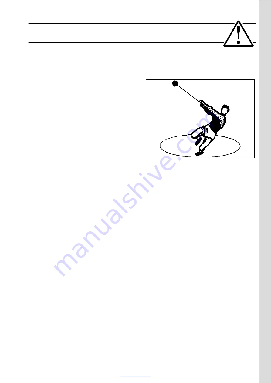
The centrifugal separator includes parts that 
rotate at high speed. This means that:

Kinetic energy is high

Great forces are generated

Stopping time is long

Manufacturing tolerances are extremely fine. 
Rotating parts are carefully balanced to reduce 
undesired vibrations that can cause a breakdown. 
Material properties have been considered 
carefully during design to withstand stress and 
fatigue.

The separator is designed and supplied for a 
specific separation duty (type of liquid, rotational 
speed, temperature, density etc.) and must not be 
used for any other purpose.

Incorrect operation and maintenance can result in 
unbalance due to build-up of sediment, reduction 
of material strength, etc., that subsequently could 
lead to serious damage and/or injury.

The following basic safety instructions therefore 
apply:

Use the separator only for the purpose 
and parameter range specified by 
Alfa Laval.

Strictly follow the instructions for 
installation, operation and maintenance.

Ensure that personnel are competent and 
have sufficient knowledge of maintenance 
and operation, especially concerning 
emergency stopping procedures.

Use only Alfa Laval genuine spare parts 
and the special tools supplied.

G

0

01

04

1

1

www.fdm.com.pe

Summary of Contents for MMPX 303SGP-11

Page 1: ...ventas fdm com pe fdmsac gmail com Movil 959440045 A L F A L A V A L S E P A R A T I O N MMPX 303SGP 11 Separator Manual Product No 881099 01 04 Book No 1270065 02 V2 www fdm com pe...

Page 2: ...S 147 80 Tumba Sweden Telephone 46 8 53 06 50 00 Telefax 46 8 53 06 50 29 Printed in Sweden 97 03 Alfa Laval Separation AB 1997 This publication or any part thereof may not be reproduced or transmitt...

Page 3: ...outine 34 5 Service Instructions 41 5 1 Periodic maintenance 42 5 2 Maintenance Logs 45 5 3 Check points at Intermediate Service 51 5 4 Check points at Major Service 63 5 5 3 year service 65 5 6 Lifti...

Page 4: ...edure 126 7 2 MMPX mechanical function 126 7 3 Purification and clarification faults 132 7 4 Purification faults 134 7 5 Clarification faults 136 8 Technical Reference 137 8 1 Technical data 138 8 2 C...

Page 5: ...lation operation service and maintenance Not following the instructions can result in serious accidents In order to make the information clear only foreseeable conditions have been considered No warni...

Page 6: ...ventas fdm com pe fdmsac gmail com Movil 959440045 6 www fdm com pe...

Page 7: ...refully all the instructions in the system documentation In addition to this separator manual a Spare Parts Catalogue SPC is supplied This separator manual consists of Safety Instructions Pay special...

Page 8: ...tling and assembly of the separator for service and repair Trouble tracing Refer to this chapter if the separator functions abnormally If the separator has been installed as part of a processing syste...

Page 9: ...ype of liquid rotational speed temperature density etc and must not be used for any other purpose Incorrect operation and maintenance can result in unbalance due to build up of sediment reduction of m...

Page 10: ...tion If incorrect vital rotating parts could unscrew Check that the gear ratio is correct for power frequency used If incorrect subsequent overspeed may result in a serious break down Welding or heati...

Page 11: ...standstill before starting any dismantling work To avoid accidental start switch off and lock power supply before starting any dismantling work Assemble the machine completely before start All covers...

Page 12: ...low lifting instructions Do not work under a hanging load Noise hazards Use ear protection in noisy environments CAUTION Burn hazards Lubrication oil and various machine surfaces can be hot and cause...

Page 13: ...icates a situation which if not avoided could result in fatal injury or fatal damage to health WARNING Type of hazard This type of safety instruction indicates a situation which if not avoided could r...

Page 14: ...ventas fdm com pe fdmsac gmail com Movil 959440045 2 Safety Instructions 14 www fdm com pe...

Page 15: ...uencing the separation result 17 3 1 2 Purification 20 3 1 3 Clarification optional 22 3 2 Design and function 24 3 2 1 Application 24 3 2 2 Design 25 3 2 3 Outline of function 25 3 2 4 Separating fun...

Page 16: ...achieved in a settling tank having outlets arranged according to the difference in density of the liquids Heavier particles in the liquid mixture will settle and form a sediment layer on the tank bot...

Page 17: ...e influences oil viscosity and density and should be kept constant throughout the separation Viscosity Low viscosity facilitates separation Viscosity can be reduced by heating Density difference The g...

Page 18: ...The throughput sets the time allowed for the separation of water and sediment from the oil A better separation result can often be achieved by reducing the throughput i e by increasing the settling t...

Page 19: ...ventas fdm com pe fdmsac gmail com Movil 959440045 19 3 Separator Basics 3 1 Basic principles of separation www fdm com pe...

Page 20: ...eparation 3 Separator Basics 20 3 1 2 Purification Centrifugal force Bowl parts Process liquid D1 Diameter of inner outlet Heavy liquid phase D2 Hole diameter of gravity disc Light liquid phase D3 Dia...

Page 21: ...action of the centrifugal force The heavy phase and any sediment move along the underside of the bowl discs towards the periphery of the bowl where the sediment accumulates The heavy phase proceeds al...

Page 22: ...com pe fdmsac gmail com Movil 959440045 3 1 Basic principles of separation 3 Separator Basics 22 3 1 3 Clarification optional Centrifugal force Process liquid Bowl parts Sediment solids G0503711 www...

Page 23: ...ocess liquid flows through the centre of the distributor The liquid flows up and is divided among the interspaces between the bowl discs where the sediment is separated from the liquid by action of th...

Page 24: ...ty 30 380 cSt 50 C Lubricating oil of R O type detergent or steam turbine The separator can be operated either as a purifier or as a clarifier When operated as a purifier the separator discharges the...

Page 25: ...rough the inlet 201 The oil is cleaned in the bowl and leaves the separator through the outlet 220 via a paring chamber Impurities heavier than the oil are collected in the sludge space at the bowl pe...

Page 26: ...is pumped by the paring disc F and leaves the bowl through the outlet 220 Separated sludge and water move towards the bowl periphery In purification separated water rises along the outside of the disc...

Page 27: ...the interface X moves inwards to a new position Y increasing the water volume in the sludge space When the sludge discharge takes place sludge and water alone are discharged Sludge discharge occurs w...

Page 28: ...losing water underneath The sliding bowl bottom is operated hydraulically by means of operating water supplied to the discharge mechanism from an external freshwater line Opening water is supplied dir...

Page 29: ...echanism Water is drained off through nozzles Y in the bowl body The sliding bowl bottom is rapidly pressed downwards by the force from the liquid in the bowl opening the sludge ports Bowl closing Aft...

Page 30: ...hich also serves as a level indicator Two identical ring shaped rubber buffers b2 support the top bearing housing The buffers are held in place by a buffer holder and form channels through which the r...

Page 31: ...ntas fdm com pe fdmsac gmail com Movil 959440045 31 3 Separator Basics 3 2 Design and function 3 2 7 Sensors and indicators Sight glass The sight glass shows the oil level in the oil sump www fdm com...

Page 32: ...et Renewal of seals in bowl and inlet outlet Major Service MS Overhaul of the complete separator including bottom part and activities included in an Intermediate Service Renewal of seals and bearings...

Page 33: ...ntents 4 1 Operating routine 34 4 1 1 Before first start 34 4 1 2 Selection of gravity disc 34 4 1 3 Start after a service 35 4 1 4 Before normal start 35 4 1 5 Starting and running up procedure 37 4...

Page 34: ...Before first start the following shall be checked 1 Ensure the machine is installed correctly and that feed lines and drains have been flushed clean 2 Fill oil in the oil sump Fill up to the middle of...

Page 35: ...he nomogram is based on the properties of fresh water in the oil For operating the separator as a clarifier the diameter of the disc should be 40 mm 4 1 3 Start after a service Pay special attention t...

Page 36: ...ection of rotation of the motor and bowl corresponds to the sign on the frame Remove the safety device A see illustration Look through the slot in the frame hood and make a quick start and stop Correc...

Page 37: ...ns occur for short periods during the starting cycle when the separator passes through its critical speeds This is normal and passes over without danger Try to learn the vibration characteristics of t...

Page 38: ...flows out through the water outlet c Start the oil feed slowly to avoid breaking the water seal Then fill the bowl as quickly as possible 7 For clarification a Start the oil feed with full flow Fill...

Page 39: ...is feed 3 Stop the separator 4 Wait until the separator has come to a complete standstill 13 15 minutes Remove the safety device and look through the slot in the frame hood to see the movement of the...

Page 40: ...filled during the run down to minimize the excessive vibration Evacuate the room The separator may be hazardous when passing its critical speeds during the run down DANGER Disintegration hazards Neve...

Page 41: ...harge mechanism 55 5 3 5 Bowl hood and sliding bowl bottom 56 5 3 6 Spindle top cone and bowl body nave 58 5 3 7 Threads of inlet pipe paring disc 59 5 3 8 Threads on bowl hood and bowl body 60 5 3 9...

Page 42: ...at must be done Daily checks consist of simple check points to carry out for detecting abnormal operating conditions Oil change interval is 1500 hours If the total number of operating hours is less th...

Page 43: ...rame feet The rubber feet get harder with increased use and age Other Check and prelubricate spindle bearings of separators which have been out of service for 6 months or longer See also 5 10 2 Before...

Page 44: ...in the service kit while assembling the separator as described in chapter 6 Dismantling Assembly on page 79 The assembly instructions have references to check points which should be carried out during...

Page 45: ...s should be carried out daily Main component and activity Part Page Notes Inlet and outlet Check for leakage Connecting housing 36 Separator bowl Check for vibration and noise 37 Belt transmission Che...

Page 46: ...an be extended from the normal 1500 hours to 2000 hours When the separator is run for short periods the lubricating oil must be changed every 12 months even if the total number of operating hours is l...

Page 47: ...ain component and activity Part Page Notes Inlet and outlet frame Clean and inspect Threads of inlet pipe 59 Paring disc 59 Housings and frame hood Separator bowl Clean and inspect Bowl hood 60 Top di...

Page 48: ...s 5 Service Instructions 48 Electrical motor Lubrication if nipples are fitted See sign on motor Signs and labels on separator Check attachment and legibility Safety label on hood 164 Other plates and...

Page 49: ...the following activities Main component and activity Part Page Notes Inlet and outlet frame Clean and inspect Threads of inlet pipe 59 Paring disc 59 Housings and frame hood Separator bowl Clean and...

Page 50: ...spindle 99 Ball bearing housing indentations 99 Check Radial wobble of bowl spindle 64 Oil sump Clean Oil sump 71 Change Oil 71 Clean and inspect Oil filling device 121 Friction coupling Clean and in...

Page 51: ...argest depth of a corrosion damage exceeds 1 0 mm or if cracks have been found Do not continue to use the separator until it has been inspected and given clearance for operation by Alfa Laval Cracks o...

Page 52: ...Inspect closely for all types of damage by corrosion and record these observations carefully Polish dark coloured spots and other corrosion marks with a fine grain emery cloth This may prevent further...

Page 53: ...using photographs plaster impressions or hammered in lead Erosion is characterised by Burnished traces in the material Dents and pits having a granular and shiny surface Parts of the bowl particularl...

Page 54: ...terials The combination of an aggressive environment and cyclic stresses will speed up the formation of cracks Keeping the machine and its parts clean and free from deposits will help to prevent corro...

Page 55: ...Pay special attention to important surfaces 1 2 3 and 4 If necessary polish with steel wool Apply a thin layer of Molykote D321R spray on all sliding surfaces and polish firmly The seal rings should b...

Page 56: ...hood seal ring at each Intermediate Service IS if the old ring is damaged or indented more than 0 5 mm Fit a new ring as follows Press the ring into the groove with a straight board 1 x 4 placed acros...

Page 57: ...Check the sealing edge a of the sliding bowl bottom If damaged through corrosion or erosion or in other ways it can be rectified by turning in a lathe Minimum permissible height of sealing edge 4 5 m...

Page 58: ...to vibrate while running Corrosion may cause the bowl to stick firmly to the spindle cone and cause difficulties during the next dismantling Remove any impact marks using a scraper and or a whetstone...

Page 59: ...n prevent correct tightening of the inlet pipe and cause the paring disc to scrape against the top disc even though the height adjustment of the paring disc has been made correctly 1 Examine the threa...

Page 60: ...Alfa Laval representative Wear If thread wear is observed mark the bowl body at the new position by punching a new alignment mark If the mark on the bowl hood passes the mark on the bowl body by more...

Page 61: ...sed by impact Clean the threads contact and guide surfaces with a suitable degreasing agent If damage is found rectify by using a whetstone or fine emery cloth Recommended grain size 240 If the damage...

Page 62: ...stance until the marks are in line with each other an extra disc must be added to the top of the disc stack beneath the top disc 3 If one or more discs have been added re check the disc stack pressure...

Page 63: ...the distance according to the illustration above Adjust the distance by adding or removing height adjusting rings 7 3 Fit the connecting housing 5 and the inlet outlet housing Tighten the nut with 30...

Page 64: ...a support and fasten it in position as illustrated 2 Remove the water tank from the frame bottom part for access to the flat belt Use the flat belt to turn the spindle 3 Permissible radial wobble max...

Page 65: ...e 5 5 3 year service Exchange of frame feet See 6 7 1 Mounting of new frame feet on page 123 Friction coupling Exchange of ball bearings see 6 3 Friction coupling on page 110 Frame intermediate part R...

Page 66: ...e distributor 2 Disconnect the motor cables 3 Tighten the frame hood 4 Fit the lifting eyes The two eyebolts must be fitted in the holes nearest to the electric motor 5 Use two endless slings to lift...

Page 67: ...nly the two special lifting eyes M12 for lifting the machine They are to be screwed into the special threaded holes Other holes are not dimensioned for lifting the machine A falling separator can caus...

Page 68: ...ve that these motors are sealed and normally they are not A water jet played on these motors will produce an internal vacuum which will suck the water between the metal to metal contact surfaces into...

Page 69: ...submerged for a long time Fuel oil sludge mainly consists of complex organic substances such as asphaltenes The most important property of a cleaning liquid for the removal of fuel oil sludge is the...

Page 70: ...to the surfaces during cleaning 1 Remove the bowl discs from the distributor and lay them down one by one in the cleaning agent 2 Let the discs remain in the cleaning agent until the deposits have be...

Page 71: ...he cover and the water tank Note that the tank must be lowered past spindle end A before it can be withdrawn B 2 Place a collecting vessel under the drain hole 3 Pull out A the oil filling device and...

Page 72: ...above middle of the sight glass Information on volume see 8 1 Technical data on page 138 7 Push in the oil filling device 8 Fit the water tank and the cover CAUTION Burn hazards The lubricating oil a...

Page 73: ...ise indicate that something is wrong Stop the separator and identify the cause Use vibration analysis equipment to periodically check and record the level of vibration The level of vibration of the se...

Page 74: ...Dismantling Remove the bearing from its seat by using a puller If possible let the puller engage the inner ring then remove the bearing with a steady force until the bearing bore completely clears th...

Page 75: ...ndling the bearings To facilitate assembly and also reduce the risk of damage first clean and then lightly smear the bearing seating on shaft spindle or alternatively in housing with a thin oil When a...

Page 76: ...ter the bearing Make sure the bearing is assembled at a right angle to the shaft spindle If necessary use a driving on sleeve that abuts the ring which is to be assembled with an interference fit othe...

Page 77: ...wiped and protected against dust and dirt If the separator has been shut down for more than 3 months but less than 12 months an Intermediate Service IS has to be made before the separator is put into...

Page 78: ...ventas fdm com pe fdmsac gmail com Movil 959440045 78 www fdm com pe...

Page 79: ...frame 99 6 2 1 Bowl spindle and frame dismantling 99 6 2 2 Bowl spindle and frame assembly 104 6 3 Friction coupling 110 6 3 1 Friction coupling dismantling 111 6 3 2 Friction coupling assembly 113 6...

Page 80: ...al tools needed for dismantling but not included in the tool kit are shown here For bowl and bowl spindle 1 Screw driver 2 Torque wrench 50 Nm with socket 16 mm 3 Pliers for internal snap ring 4 Ball...

Page 81: ...g ring 8 Frame hood 9 Lock ring 10 Heavy phase cover 11 Gravity disc Clarifier disc 12 Leader cone 13 Paring chamber cover The connecting housing is removed from the frame hood top at paring disc adju...

Page 82: ...om Movil 959440045 82 14 Inlet pipe 15 Bowl hood 16 Top disc 17 Bowl discs 18 Wing insert 19 Bowl discs 20 Distributor 21 Sliding bowl bottom IS Intermediate service kit MS Major service kit Left hand...

Page 83: ...om Movil 959440045 83 22 Cap nut 23 Upper distributing ring 24 Valve plug 25 Operating slide 26 Lower distributing ring 27 Bowl body 28 Nozzle IS Intermediate service kit MS Major service kit Left han...

Page 84: ...ibreboard or a suitable pallet 1 Remove safety device 1 and look through the slot in the frame hood to see if the bowl still rotates The bowl parts can remain very hot for a considerable time after th...

Page 85: ...off heavy phase cover 10 gravity disc clarifier disc 11 and leader cone 12 6 Carefully prise loose paring chamber cover 13 by using a screwdriver Lift off the paring chamber cover 7 Lift out inlet pip...

Page 86: ...ol and screw down the central screw b until it stops Compress the disc stack by tightening the nut c firmly 9 Unscrew bowl hood 15 clockwise by using a tin hammer Left hand thread 10 Lift off the bowl...

Page 87: ...inst a firm base This will facilitate loosening of the top disc 12 Lift out sliding bowl bottom 21 using the special tool Ease the sliding bowl bottom off with the central screw of the tool If necessa...

Page 88: ...e central screw of the tool If necessary knock on the handle 19 Soak and clean all parts thoroughly in suitable cleaning agent see 5 7 1 Cleaning agents on page 69 20 Clean nozzles 28 in bowl body 27...

Page 89: ...bowl assembly Make sure that the following check points are carried out before and during assembly of the separator bowl Corrosion Erosion Cracks Bowl spindle cone and bowl body nave Threads on bowl h...

Page 90: ...ting ring 24 Valve plug 25 Operating slide 26 Lower distributing ring 27 Bowl body 28 Nozzle IS Intermediate service kit MS Major service kit Left hand thread NOTE Be sure bowl parts are not interchan...

Page 91: ...6 Top disc 17 Bowl discs 18 Wing insert 19 Bowl discs 20 Distributor 21 Sliding bowl bottom IS Intermediate service kit MS Major service kit Left hand thread NOTE Be sure bowl parts are not interchang...

Page 92: ...9 Lock ring 10 Heavy phase cover 11 Gravity disc Clarifier disc 12 Leader cone 13 Paring chamber cover The connecting housing is removed from the frame hood top at paring disc adjustment Major Service...

Page 93: ...dy 27 on the spindle Avoid damaging the spindle cone Attach the special lifting tool to the bowl body nave Screw down the central screw of the tool then lower the bowl body until the screw rests on th...

Page 94: ...e e and groove f respectively 7 Screw cap nut 22 counter clockwise onto the spindle Tighten firmly Left hand thread 8 Fit sliding bowl bottom 21 Make sure that the square seal ring lies concentrically...

Page 95: ...istributor fit properly into the holes of the top disc 10 Fit the disc stack assembly in the bowl body Make sure that the cuts in the wings on the underside of the distributor fit properly in the corr...

Page 96: ...ammer Strike the spanner handle until the bowl hood lies tightly against the bowl body In a new bowl the assembly marks now will be in line with each other See also 5 3 8 Threads on bowl hood and bowl...

Page 97: ...chamber cover 13 by pressing it down gently 16 Assemble leader cone 12 gravity disc clarifier disc 11 and heavy phase cover 10 17 Fit lock ring 9 Apply a thin layer of Molykote Paste 1000 to the thre...

Page 98: ...the bowl by means of the flat belt If the bowl does not rotate freely or a scraping noise is heard incorrect bowl assembly or incorrect height adjustment of the paring disc can be the cause 20 Make s...

Page 99: ...r if the separator vibrates while running see Check point 5 4 2 Radial wobble of bowl spindle on page 64 MS Parts to be renewed at Major Service 1 Lip seal ring 2 Screen 3 Gasket 4 Frame top part 5 De...

Page 100: ...er screws 2 Remove the water tank 3 Remove the flat belt 4 Remove the screws and lift off frame top part 4 Lip seal ring 1 must be removed in the case of Major Service or if found damaged 5 Clean the...

Page 101: ...fer 10 7 Screw the cap nut counter clockwise left hand thread onto the spindle top to protect the top and bore Lift out spindle assembly 11 rubber buffer 10 and O ring 20 Remove snap ring 14 by using...

Page 102: ...n damaged 9 Remove the belt pulley 17 10 Lubricate the mounting dismantling tool Fit the mounting dismantling tool and screw it down as far as it will go 1 Use a long spanner 450 650 mm to press the b...

Page 103: ...n any service kit but must be ordered separately 14 Remove the screen 2 from the frame top part 4 Discard the gasket 3 This gasket is not included in any service kit but must be ordered separately 15...

Page 104: ...eflector ring 6 Top bearing cover 7 Gasket 8 Fan 9 Buffer holder 10 Rubber buffer 11 Bowl spindle 12 Ball bearing holder 13 Ball bearing 14 Snap ring 15 Ball bearing 16 Oil pump 17 Belt pulley 18 Pump...

Page 105: ...it a new O ring 22 and assemble the frame intermediate part 21 Use a torque wrench and tighten the screws lightly crosswise at first Then tighten all around to 45 Nm Secure the screws with Loctite 242...

Page 106: ...unting tool from the tool kit 4 Fit oil pump 16 and belt pulley 17 Make sure that the recess in the belt pulley fits over the guide pin in the oil pump Heat the belt pulley in a heating cabinet to 250...

Page 107: ...bearing holder 12 and secure it with snap ring 14 Fit O ring 20 and rubber buffer 19 Lower spindle assembly 11 carefully into the separator intermediate frame NOTE Do not fit the pump sleeve until th...

Page 108: ...the lugs in the fan enter the recesses in the bowl spindle Before tightening make sure that there is some play a between top bearing cover 6 and the frame The play will disappear when the screws are t...

Page 109: ...the screws of the top frame using a torque wrench width across flats 16 mm Tighten the screws slightly crosswise at first Then tighten all around to 45 Nm Secure the screws with Loctite 242 11 Fit and...

Page 110: ...laced with new ones or be thoroughly cleaned from grease DANGER Entrapment hazards Make sure that rotating parts have come to a complete standstill before starting any dismantling work G0372121 1 Snap...

Page 111: ...4 Remove the flat belt 5 Remove the electric motor complete with the friction coupling and motor adapter Weight of motor including adapter and friction coupling is not more than 20 kg 6 Remove snap ri...

Page 112: ...e off the coupling 9 Remove snap rings 1 and 2 and drive off coupling hub 6 Turn the coupling i e belt pulley 5 with bearings 3 the other way round and drive off the ball bearings and washer by using...

Page 113: ...of ball bearings 3 Knock down the bearings carefully do not forget washer 4 by using the tube which must rest on the outer race of the bearing The new bearings must not be heated as they are packed wi...

Page 114: ...n coupling onto the shaft 5 Fit the screw 12 with the washer 11 and spring washer 10 to secure the friction coupling Assembly of friction elements 6 Fit new friction elements 7 cover 8 and snap ring 9...

Page 115: ...adapter and friction coupling in position Also lubricate the threads of the belt tightener with Molykote 1000 paste or similar 8 Fit and tighten the flat belt see 6 4 1 Belt replacement and tightenin...

Page 116: ...he retightening has been done after approximately 24 hours of operation 6 4 1 Belt replacement and tightening If only tightening of flat belt should be done only steps 3 and 7 11 have to be performed...

Page 117: ...re it can be withdrawn B 2 Check that the belt tightener is in backward position 3 Loosen but do not remove the motor adapter screws NOTE Pay attention to the air gap A between the cup springs and the...

Page 118: ...that there is a sufficient film of Molykote 1000 Paste or an equivalent lubricating paste between the adapter and the frame surface Lower the motor after checking Fit the motor adapter screws but do...

Page 119: ...shaft 1 further until the threaded sleeve 2 and dog 3 are disengaged Shake the motor by hand several times during this operation in order to overcome the friction between the motor adapter and the fra...

Page 120: ...roceed to step 13 13 Fit the water tank and cover 14 The separator may now be started NOTE If the springs 4 are not decompressed they will loose their tension and correct tightening of belt will be im...

Page 121: ...ss 7 with a degreasing agent 2 Fit the new plate on the outside of the sight glass The plate is self adhesive 3 Mark the position of the plate relative to the recess in sleeve 1 Assemble the oil filli...

Page 122: ...k that the pipes are not defective Replace if necessary If the parts fitted on the cover have been removed it is necessary to fit the parts properly together at assembly Seal the drain pipe and water...

Page 123: ...ng the separator Follow 5 6 Lifting instructions on page 66 1 Loosen the foundation bolts and lift the separator 2 Remove the existing frame feet 3 Mount the new feet 4 Place the separator in its orig...

Page 124: ...ventas fdm com pe fdmsac gmail com Movil 959440045 124 www fdm com pe...

Page 125: ...ed too high 130 7 2 10 Speed too low 131 7 2 11 Water in oil sump 131 7 3 Purification and clarification faults132 7 3 1 Liquid flows through bowl casing drain and or sludge outlet 132 7 3 2 Bowl open...

Page 126: ...still is not solved contact your Alfa Laval representative 7 2 MMPX mechanical function 7 2 1 The separator does not start 7 2 2 Start up time too long 7 2 3 Starting power too low See 7 2 2 Possible...

Page 127: ...ower too high Possible cause Action Motor failure Repair the motor 50 Hz pulley running on 60 Hz power supply After immediate stop install correct pulley Height position of paring disc incorrect Check...

Page 128: ...or cleaning incorrect assembly too few discs insufficiently tightened bowl hood bowl assembled with parts from other separators Incorrectly tightened bowl hood involves fatal danger Height adjustment...

Page 129: ...er discharge a vibrating separator Possible cause Action Uneven sludge deposits in sludge space See 7 4 Purification faults and 7 5 Clarification faults Bearing damaged or worn Fit new bearings Vibrat...

Page 130: ...o low Read oil level and add oil if necessary Height adjustment of paring disc is incorrect Check and adjust Top and or bottom bearing damaged or worn Fit new bearings Possible cause Action Incorrect...

Page 131: ...ion too loose Tighten the belt Motor failure motor bearings Repair the motor Bearing overheated damaged or worn Fit new bearings Incorrect transmission 60 Hz pulley running on 50 Hz power supply Make...

Page 132: ...ter pressure Straighten the hose Clean the strainer Check the water pressure Seal ring on gravity disc clarifier disc defective Fit a new seal ring Seal ring in sliding bowl bottom defective Install a...

Page 133: ...sleeve Valve plugs defective Install new valve plugs Sludge deposits on operating slide Clean the operating slide Valve for operating water not closing properly Can result in repeated discharges Open...

Page 134: ...pace in bowl is filled with sludge Clean the bowl and shorten time between discharges Disc stack clogged Clean the bowl discs Inlet clogged Clean Bowl speed too low See 7 2 10 Speed too low on page 13...

Page 135: ...losed Open the valve s and adjust the back pressure to normal value Sealing water volume too small Check water supply Disc stack clogged Clean the bowl discs Seal ring on gravity disc clarifier disc d...

Page 136: ...b Readjust time between discharges c Re assemble and operate the separator as a purifier Sludge space in bowl filled with sludge Clean the bowl and shorten time between discharges Disc stack clogged C...

Page 137: ...n chart 147 8 5 2 Alfa Laval lubricating oil groups 148 8 5 3 Recommended lubricants 150 8 5 4 Recommended lubricating oils 152 8 5 5 Recommended oil brands 153 8 6 Drawings 156 8 6 1 Basic size drawi...

Page 138: ...ty Maximum 1 7 m3 h Rated capacity1 1700 litres hour Maximum density feed sediment 1100 kg m3 2631 kg m3 Operating liquid Max density 1000 kg m3 Min pressure 150 kPa See also 8 4 Water quality on page...

Page 139: ...ge volume 1 litre nominal fixed Discharge interval minimum 2 minutes Required water quality See 8 4 Water quality on page 146 Lubrication See 8 5 Lubricants on page 147 Lubricating oil volume 0 5 litr...

Page 140: ...iscs stainless steel Other bowl parts brass Oil paring disc brass Other inlet and outlet parts stainless steel brass cast iron 1 An epoxy enamel NOTE The separator is a component operating in an integ...

Page 141: ...w 5 5 litres minute Pressure 150 600 kPa 220 Outlet for light phase oil Counterpressure Maximum 360 kPa 221 Outlet for heavy phase water No counterpressure 222 Outlet for solid phase The outlet after...

Page 142: ...eous flow 0 9 litre per minute Quality requirements See 8 4 Water quality on page 146 Pressure 150 600 kPa Consumption 0 9 litre per discharge 377 Outlet for operating liquid open 462 Drain of frame t...

Page 143: ...still Ready for start means The machine is assembled correctly All connections are installed according to Connection List Interconnection Diagram and Interface Description Start means The power to th...

Page 144: ...ped in a way that is described in EN 418 8 3 3 Component description and signal processing Separator motor 701 The separator is equipped with a 3 phase DOL direct on line started motor The separator c...

Page 145: ...ntas fdm com pe fdmsac gmail com Movil 959440045 145 Function graph and running limitations A Stand still B Starting mode C Running mode D Stop mode E Safety stop mode A B C D E G0543211 www fdm com p...

Page 146: ...can build up if the water is hard corresponds to 10 dH or 12 5 E Increased operating temperature accelerates the chalk built ups 3 Chloride content 100 ppm NaCl equivalent to 60mg Cl l Chloride ions c...

Page 147: ...icating oil 4 Bowl Some of the guide surfaces sliding contact surfaces and lock ring joint Pressure loaded surfaces Threads of cap nut Screw head joints Tools Pastes as specified in 8 5 3 Recommended...

Page 148: ...to avoid mixing of different types of oil Even a few drops of motor oil mixed into a synthetic oil may result in severe foaming Any presence of black deposits in a mineral type oil is an indication th...

Page 149: ...brands and other lubricants than recommended is done on the exclusive responsibility of the user or oil supplier Applying handling and storing of lubricants Always be sure to follow lubricant manufact...

Page 150: ...or 805 K varnish 901 Gleitmo Paste G rapid 537086 04 All pressure loaded surfaces Dow Corning Molykotepaste1000 sprayD321 R varnishD321 R 537086 02 535586 01 535586 02 Rocol Antiscuffing paste ASP Kl...

Page 151: ...2 Energrease LS2 Castrol Spheerol SW2 EP Spheerol EPL2 Chevron Duralith grease EP2 Exxon Beacon EP2 Mobil Mobilith SHC 460 Mobilux EP2 Gulf Gulflex MP2 Q8 Rembrandt EP2 Shell Cailithia EP Grease T2 Al...

Page 152: ...for short periods lubricating oil must be changed every 12 months even if the total number of operating hours is less than stated in the recommendations above Check and prelubricate spindle bearings...

Page 153: ...4 2 According to ISO 2909 Manufacturer Designation Alfa Laval 546098 80 20 litres 546098 81 4 litres 546098 82 208 litres 546098 83 1 litre BP Bartran 150 Castrol Alpha ZN 150 Esso Exxon Statoil Teres...

Page 154: ...30 1 According to ISO 3448 3104 2 According to ISO 2909 Manufacturer Designation Alfa Laval 542690 80 20 litres 542690 81 4 litres 542690 82 208 litres 542690 83 1 litre BP Enersyn HTX 220 Castrol Alp...

Page 155: ...ventas fdm com pe fdmsac gmail com Movil 959440045 155 www fdm com pe...

Page 156: ...il com Movil 959440045 156 8 6 Drawings 8 6 1 Basic size drawing Alfa Laval ref 557494 Connections 201 and 220 are turnable Vertical force not exceeding 5 kN foot Horizontal force not exceeding 7 kN f...

Page 157: ...n Alfa Laval ref 557494 A Maximum horizontal displacement at the inlet outlet connections during operation 20 mm B Maximum vertical displacement at the solid phase outlet connection during operation 1...

Page 158: ...c gmail com Movil 959440045 158 8 6 3 Dimensions of connections Alfa Laval ref 557494 Data for connections see 8 2 Connection list on page 141 All connections to be installed non loaded and flexible G...

Page 159: ...ventas fdm com pe fdmsac gmail com Movil 959440045 159 www fdm com pe...

Page 160: ...DdelB3 feb1983 Standards IEC 34 1 IEC 72 2 Size 90L Type MT90L Weight 16 kg Poles 2 Insulation class F Bearings DE 6305 C3 NDE 6204 C3 Method of cooling IC 41 IEC 34 6 Specification TEFC standard moto...

Page 161: ...liano Navale RINA USSR Register of Shipping RSU Required classification society must always be specified when ordering Factory test certificate to be enclosed at the delivery Article No kW Speed RPM F...

Page 162: ...C 72 Size 90L Type MBT 90 LB Weight 16 kg Poles 2 Insulation class F Bearings DE 6205 Z NDE 6205 Z Method of cooling IC 41 IEC 34 6 Specification Totally enclosed three phase motor for marine service...

Page 163: ...Society NKK Essential Service Required classification society must always be specified when ordering Factory test certificate to be enclosed at the delivery Rated output kW valid for temperature rise...

Page 164: ...on of rotation bowl Speed motor shaft El current frequency Recommended motor power Max density of feed Max density of sediment Process temperature min max MMPX 303SGP 11 XXXX 881099 01 04 544468 01 54...

Page 165: ...sive vibration occur stop separator and keep bowl filled with liquid during rundown Out of balance vibration will become worse if bowl is not full Separator must stop rotating before any dismantling w...

Page 166: ...ventas fdm com pe fdmsac gmail com Movil 959440045 166 8 6 6 Gravity disc nomogram G0074931 Oil density kg m3 at 15 oC Gravity disc hole diameter mm www fdm com pe...

Page 167: ...the correct gravity disc has a hole diameter of 52 mm Example II in nomogram Reference in graph _ _ _ _ _ _ _ From the graphs broken line the correct gravity disc has a hole diameter of 66 mm Oil den...

Page 168: ...Storage Specification Upon arrival to the store check all components and keep them 1 Well stored and protected from mechanical damage and theft 2 Dry an protected from rain and humidity 3 Organized in...

Page 169: ...ter tight The separator must be stored in a dry storage room protected from rain and humidity In a special water resistant box for outdoor storage The separator and its parts have been treated with an...

Page 170: ...rted separately When lifting a separator it must always be hung securely See details in chapter 5 6 Lifting instructions on page 66 During erection all inlets and outlets to separators and accessories...

Page 171: ...and operation so that instruments are easily visible Valves and controls must be within convenient reach Pay attention to space requirements for maintenance work work benches dismantled machine parts...

Page 172: ...r oil changing Specification The oil filling device must not be blocked by floor plate arrangement etc Recommendation It should be possible to place a portable collecting tray under the oil filling de...

Page 173: ...ws Check that the bolts do not press against the edges of the holes otherwise the elasticity of the mounting of the separator frame will be impeded Fit height adjusting washers required Check that the...

Page 174: ...ventas fdm com pe fdmsac gmail com Movil 959440045 174 www fdm com pe...

Page 175: ...ive Alfa Laval Separation AB Separator Manuals dept SKL S 147 80 Tumba Sweden Fax 46 8 53065029 Your name Company Address City Country Product MMPX 303SGP 11 Book No 1270065 02 V2 Date Yes No Is it ea...

Page 176: ...ventas fdm com pe fdmsac gmail com Movil 959440045 176 www fdm com pe...

Page 177: ...s page and give it to your local Alfa Laval representative who will advise you of current prices Your local Alfa Laval representative will also be able to help you with information regarding any other...

Page 178: ...ventas fdm com pe fdmsac gmail com Movil 959440045 178 www fdm com pe...

Page 179: ...one and bowl body nave 58 Threads of inlet pipe 59 Threads on bowl hood and bowl body 60 Clarification 22 Clarifier 28 Clarifier disc 28 Cleaning 68 Connections Connection list specifications 141 Dime...

Page 180: ...lume 139 Operation 33 P Periodic maintenance 42 Power consumption 138 Power transmission mechanical Belt drive 30 Bowl spindle 30 Friction coupling 30 Purification 20 Purifier bowl Characteristic part...

Page 181: ...ventas fdm com pe fdmsac gmail com Movil 959440045 181 W Warning signs 13 Water Water quality specifications 146 www fdm com pe...

Reviews: