


28/33
ALFA IN a.s. ©
www.alfain.eu
1,6
16
16 * 60 = 960
2,0
20
20 * 60 = 1200
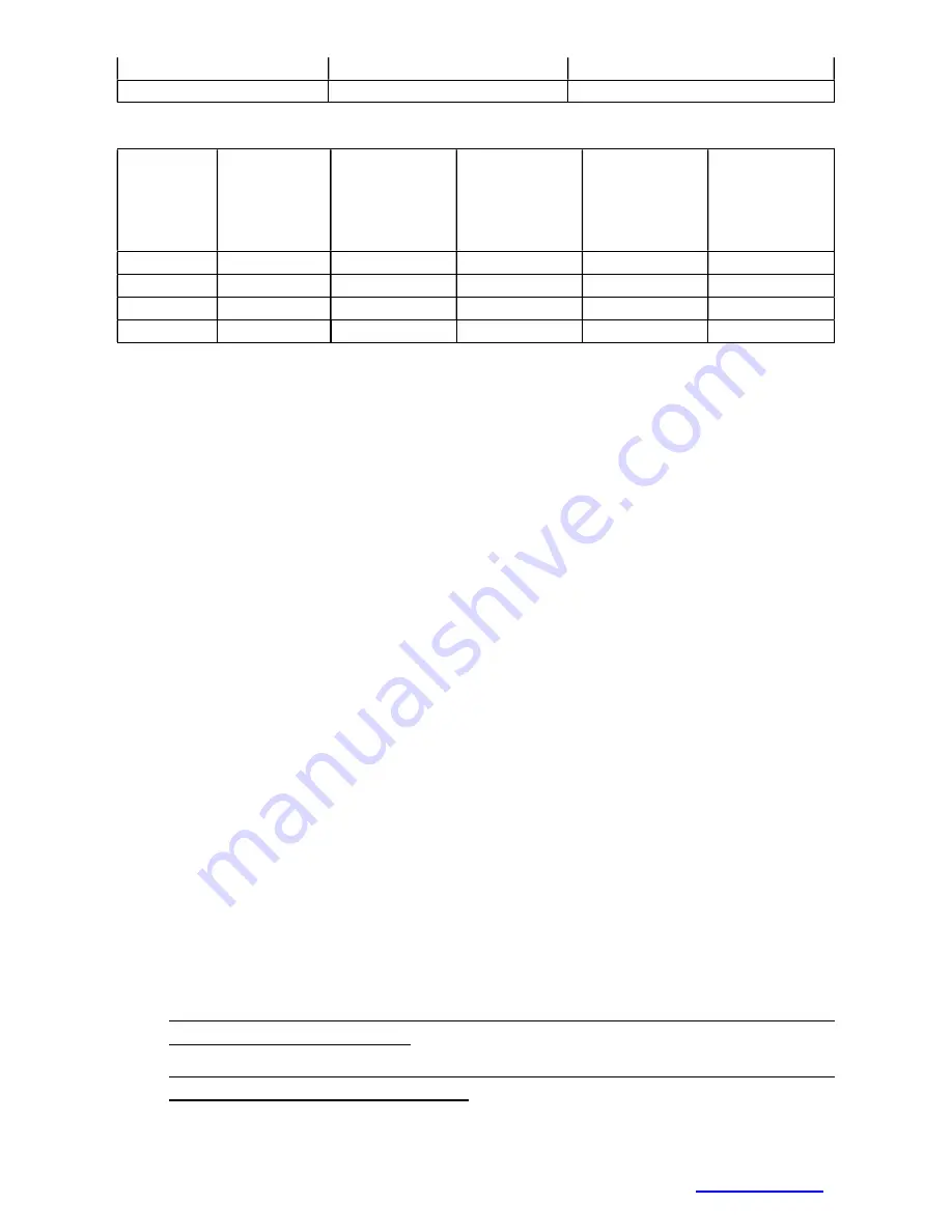
TABLE OF ELECTRODE CONSUMPTION DURING WELDING
Electrode
diameter
[mm]
Welding
current
range [A]
Electrode
length [mm]
Weight of
welded
electrode
without slag
[g]
Electrode
welding time
[s]
Weight of
welded
electrode
without slag
in 1 s [g/s]
1,6
30 - 55
300
4
35
0,11
2,5
70 - 110
350
11
49
0,22
3,2
90 - 140
350
19
60
0,32
4,0
120 - 190
450
39
88
0,44
13 MMA WELDING (ELECTRIC WELDING - ELE)
9. Select the
MMA
method according to SELECTION OF THE WELDING
METHOD.
10.
Disconnect the connecting cable
A2
, connect the electrode holder to
the quick connector
A8.
11.
The left display
V10
shows the set value of the welding current, the
right display
V11
shows the abbreviation ELE.
12.
Set the value of the welding current using encoder
V5
.
13.
During welding, the welding current is measured on display
V10
and
the voltage on display
V11
.
14.
After the welding is finished, the measured value (
HOLD
) remains
on the display for 6 s.
15.
If a torch with a remote control is connected, ELE is shown on its
display.
16.
If the MIG/MAG torch remains connected, the welding voltage
will be on it!
14 MAINTENANCE AND SERVICE TESTS
The equipment requires minimal care and maintenance under normal working
conditions. Certain principles must be observed to guarantee faultless operation
and long service life:
1. The machine may only be opened by our service personnel or a trained
electrician.
2. Occasionally, the condition of the mains plug, mains cable and welding
cables should be checked.
3. Once or twice a year, blow out the entire plant with pressurised air,
especially the aluminium cooling profiles. Beware of the risk of damage to
electronic components by direct compressed air from a short distance!