


14/33
ALFA IN a.s. ©
www.alfain.eu
INTRODUCTION OF THE WELDING WIRE INTO THE TORCH AND
CONNECTION OF THE EARTHING CABLE
1. Connect the grounding pliers to the welding machine or welding table.
2.
Caution
Do not point the torch against the eyes when inserting the
wire!
3. Screw the central torch tip to the
A3
connector on the machine with the
machine switched off.
4. Remove the gas nozzle from the Torch.
5. Unscrew the current feedthrough.
6. Connect the machine to the network.
7. Turn the main switch to position I.
8. Press button
A13
located in the feed area of the machine to start the feed
motor. The welding wire is fed into the torch. After the wire has been run
out of the torch tube, screw on the current pass and the gas nozzle.
9. Before welding, spray the area in the gas nozzle and the jet line with a
separating spray to prevent spatter from sticking.
GAS FLOW ADJUSTMENT
The electric arc and the melt bath must be perfectly protected by gas. Too little
gas cannot create the necessary protective atmosphere; on the contrary, too
much gas entrains air into the electric arc.
Warning
The gas cylinder must be well secured against falling. This
manual does not address the safe securing of the gas cylinder. Information can
be obtained from the supplier of industrial gases.
1. Attach the gas hose to the gland on the rear panel of the machine.
2. Press button
V1
(fig. 7) on the main panel to switch on the gas valve. If the
button is pressed for less than 3 s, the gas valve will be switched off when
the button is released. If the button press time is longer than 3 s, the gas
valve will be switched off after approx. 20 s or after pressing any button.
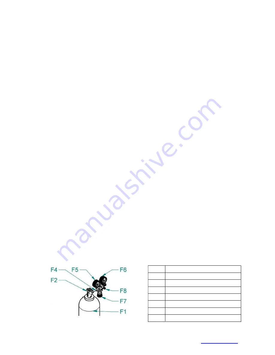
3. Turn the adjusting screw
F7
on the bottom of the pressure reducing valve
until the flow meter
F6
shows the desired flow, then release the button.
The optimum flow rate is 10-15l/min.
4. After a prolonged machine shutdown or torch change, it is advisable to
purge the pipe with shielding gas before welding.
Figure 6 - Gas flow settings
Item. Description
F1
Bottle
F2
Bottle valve
F4
Reducing valve
F5
High pressure manometer
F6
Low pressure manometer
F7
Adjusting screw
F8
Gas valve