DISASSEMBLY INSTRUCTIONS
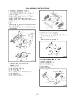
1-4: LOCATION OF PRINTED CIRCUIT BOARDS
(Refer to Fig. 1-4)
CAUTION: BEFORE ATTEMPTING TO REMOVE OR
REPAIR ANY PCB, UNPLUG THE POWER
CORD FROM THE AC SOURCE.
Syscon PCB
IF PCB
Operation 1 PCB
Head Amp PCB
Fig. 1-4
1-5: MAIN PCB (Refer to Fig. 1-5)
1.
2.
3.
Remove the 5 screws
1
.
Remove the screw
2
.
Unlock the 2 supports
3
and remove the Main PCB in
the direction of the arrow.
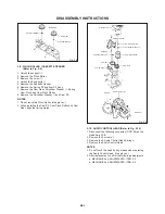
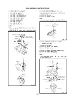
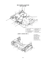
FRONT LOADING UNIT 9, CHASSIS SECTION, JACK
PLATE AND SYSCON PCB (Refer to Fig. 1-7-A)
1-7:
1.
2.
3.
4.
5.
6.
7.
8.
9.
10.
11.
Remove the screw
1
.
Remove the screw
2
.
Remove the screw
3
.
Remove the Front Loading Unit 9 in the direction of arrow
(A).
Remove the 3 screws
4
.
Remove the 2 screws
5
.
Remove the Chassis Section in the direction of arrow (B).
Remove the 2 screws
6
.
Unlock the 2 supports
7
and remove the Jack Plate in
the direction of arrow (C).
Remove the screw
8
.
Unlock the support
9
and remove the Syscon PCB.
NOTE
When installing the Front Loading Unit 9, align the
timing marks and pull the Cassette Holder Ass'y in the
direction of arrow (D). (Refer to Fig. 1-7-B)
Front Loading Unit 9
(A)
4
7
7
Jack Plate
(C)
4
Chassis Section
Deck Holder
Syscon PCB
3
4
9
2
1
6
6
5
5
(B)
8
Operation 1 PCB
(D)
Cassette Holder Ass'y
Marker
Fig. 1-7-A
Fig. 1-7-B
3
TV PCB Holder Ass'y
Main PCB
1
1
2
1
3
1
1
Fig. 1-5
1-6: TOP SHIELD PLATE AND BOTTOM SHIELD PLATE
(Refer to Fig. 1-6)
1.
2.
3.
4.
Remove the 4 screws
1
.
Remove the Top Shield Plate in the direction of arrow
(A).
Remove the screw
2
.
Remove the Bottom Shield Plate in the direction of
arrow (B).
Fig. 1-6
1
1
1
1
(B)
Syscon PCB
(A)
Top Shield
Plate
Bottom Shield Plate
2
B1-2


