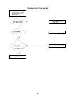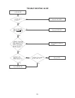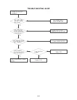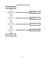
ELECTRICAL ADJUSTMENTS
4-15: SUB COLOR (TV)
1.
2.
3.
4.
5.
Receive the color bar pattern (RF Input).
Connect the oscilloscope to TP801.
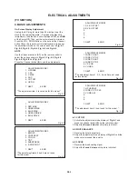
Activate the adjustment mode display of Fig. 4-3 and
press the channel button (3) on the remote control.
Adjust the VOLTS RANGE VARIABLE knob of the
oscilloscope until the range between white 100% and
0% is set to 4 scales on the screen of the oscilloscope.
Press the VOL. UP/DOWN button on the remote control
until the red color level is adjusted to 85% of the white
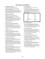
level. (Refer to Fig. 4-8)
4-16: SUB COLOR (AV)
1.
2.
3.
4.
5.
Receive the color bar pattern (Audio Video Input).
Connect the oscilloscope to TP801.
Activate the adjustment mode display of Fig. 4-3 and
press the channel button (3) on the remote control.
Adjust the VOLTS RANGE VARIABLE knob of the
oscilloscope until the range between white 100% and
0% is set to 4 scales on the screen of the oscilloscope.
Press the VOL. UP/DOWN button on the remote control
until the red color level is adjusted to 85% of the white
level. (Refer to Fig. 4-8)
4-17: SUB TINT (AV)
1.
2.
3.
4.
Receive the NTSC rainbow pattern (Audio Video Input).
Connect the oscilloscope to TP803.
Activate the adjustment mode display of Fig. 4-3 and
press the channel button (4) on the remote control.
Press the VOL. UP/DOWN button on the remote control
until the waveform becomes as shown in Fig. 4-9.
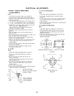
Fig. 4-9
0%
85%
100%
4-18: CONSTANT VOLTAGE
1.
2.
3.
Set to the AV mode. (No input for AV)
Connect the DC voltmeter to TP401.
Adjust the VR502 until the DC voltmeter is 103
±
0.5V.
Fig. 4-8
D3-4

