MECHANICAL ADJUSTMENTS
1-4: CONFIRMATION OF FAST FORWARD TORQUE
1.
2.
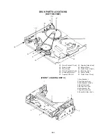
Set torque gauge (JG002G) on take-up reel disk, and
place unit in FAST FORWARD mode. (Refer to Fig. 1-4)
Confirm that torque is more than 400gf•cm.
NOTE
After setting the torque gauge on the reel disk, hold the
gauge in place.
Push the FAST FORWARD button and the reel disk will
begin to turn.
1-5: CONFIRMATION OF REWIND TORQUE
1.
2.
3.
Operate within 4 or 5 seconds after the reel disk begins
to turn.
Set torque gauge (JG002G) on supply reel disk, and
place the unit in REWIND mode. (Refer to Fig 1-4).
Confirm that torque is more than 400gf•cm.
NOTE
After setting the torque gauge on the reel disk, hold the
gauge in place.
Push the REWIND button and the reel disk will begin to
turn.
1-6: CONFIRMATION OF REEL BRAKE TORQUE
(Take-Up Reel Brake) (Refer to Fig. 1-4)
1.
2.
3.
Set to STOP mode.
Set the torque gauge (JG002G) to the take-up reel and
turn it counterclockwise.
Confirm that it is more than 200gf•cm at that time.
(Supply Reel Brake) (Refer to Fig. 1-4)
1.
2.
3.
Set to STOP mode.
Set the torque gauge (JG002G) to the supply reel and
turn it clockwise.
Confirm that it is more than 200gf•cm at that time.
NOTE
Separate the idler from the reel and confirm the brake
torque.
2-1: GUIDE ROLLER
NOTE
If the torque value checked is out of tolerance, replace
the appropriate parts as follows.
2. TAPE RUNNING CONFIRMATION
AND ADJUSTMENT
Tape running is adjusted precisely at the factory.
Normally, it is not necessary to make adjustments.
It is necessary to confirm and make adjustments
when the parts of the tape running mechanism are
replaced because of extensive usage or failure.
1.
2.
3.
4.
5.
6.
Connect CH-1 on the oscilloscope to TP4002 (PB Envelope)
and CH-2 to TP4001 (SW Pulse).
Set the tracking to manual center position in the following
way. Press and hold the tracking auto button more than 2
seconds to set the tracking to center position.
Trigger with SW pulse and observe the envelope.
(Refer to Fig. 2-1-A)
Adjust the guide roller height while observing the envelope,
and make the envelope flat. Adjust the envelope so that
the flatness will not be affected even when the tracking
control button is pressed. (Use the adjustment screwdriver
JG005).
Press and hold the tracking control button and (at the point
that the envelope waveform starts to reduce) adjust the
envelope so that the A : B ratio is better than 3 : 2.
(Refer to Fig. 2-1-B)
Adjust the PG shifter (ELECTRICAL ADJUSTMENTS :
ITEM 3-1) in the PLAY mode.
NOTE
After adjustment, confirm and adjust A/C head tilt.
(Refer to item 2-2)
Torque Gauge
Check Items
Replace Parts
1-4
Idler Ass'y or Clutch ASS'Y
1-5
Idler Ass'y or Clutch ASS'Y
1-6
Main Brake T Ass'y or Main Brake
S Ass'y
CH-2
Track
CH-1
Track
CH-1
PB Envelope
(TP4002)
CH-2
SW Pulse
(TP4001)
Fig. 1-4
Fig. 2-1-A
D1-2


