PREPARATION FOR SERVICING
How to use the Servicing Fixture
1.
2.
3.
4.
Unplug the connector CP301, CP353, CP810, CP820, CP850 and CP005, then remove the VCR Block from the set.
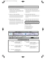
Connect as shown in the below figure using the Service Fixture.
• Connect the Syscon PCB to the Main PCB with the cable JG162A and JG162H.
• Connect the Syscon PCB to the CRT PCB with the cable JG162Y.
Short circuit between TP1001 and Ground with the cable JG154.
(Refer to MAJOR COMPONENTS LOCATION GUIDE)
The EOT, BOT and Reel Sensor do not work at this moment.
At that time, the STOP/EJECT button is available to insert and eject the Cassette Tape.
CP850
CP820
JG162Y
Syscon PCB
IF PCB
To Main PCB
(CD820)
Operation 1 PCB
Head Amp PCB
Deck Chassis
JG162A
To Main PCB
(CD810)
To CRT PCB
(CD850)
JG162H
CP810
TP1001
JG154
To Ground
C5-2


