Airzone iQ Zone Installation Manual Download Page 9


4. ZONING SYSTEM OPERATION 


Some important characteristics of the iQ Zoning System are: 
 

A)  It operates with 12 VDC 
B)  It runs a single 4 conductor, stranded and shielded cable to all system elements 
C)  The dampers are powered open/powered close 
D) The way the Airzone Controller communicates with the Zone Control Modules is based 

on a communication protocol. 

E)  It communicates with the iQ Controller over two data wires. 

 
Because of the flexibility of the Zoning System, and the High Performance objectives, each 
zone requires the setting of some basic parameters in order to activate the system. Those 
parameters must be set by the installer at the initial power on of the Zoning System and before 
enabling the Zoning from the iQ Controller. Those basic parameters will indicate: 
 

1)  if the Zone Control Module will be a Master or Subordinate 
2)  the Zone Control Module address 
3)  Zone weight for a Master Zone Control Module 
4)  Master Zone number if the Module is defined as a Subordinate.  

 
Each individual Zone Control Module requires a different address to be able to communicate 
with the Airzone Controller. Zone Control Modules that will have a Thermostat connected to 
them will have addresses ranging from 1 to 8, and they are called “Master Zone Control 
Module”, while Zone Control Modules that will follow a given Master Controller, will have 
addresses ranging from 9 through 32. Those Zone Control Modules are called “Subordinate 
Zone Control Modules”.  
While the Master Zone Control Module will have stored the Zone Weight, the Subordinate 
Controller will store the Address of the Master Zone Controller to which it is subordinated. 
 
Subordinate Zone Control Modules have to be used when a given zone requires the use of 
more than one damper, because of the ductwork layout. In such a situation, to allow the whole 
zone to be properly conditioned, all dampers will need to be controlled by the single Thermostat 
connected to the Master Zone Control Module. 
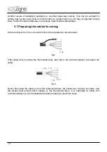
5. WIRING 


The Zoning System wiring is very simple, but great care must be taken during its lay out and 
connection. All wiring must be laid out with Plenum Cable, AWG20, Shielded type Belden 
6402FE or equivalent. The cable should NOT be stapled in place. If it is required to have the 
cable fixed to any part of the building structure, clamps with cable protection should be used. 
DO NEVER strangle the cable.  
 
Failure to follow these recommendations may result in an unreliable installation  that will 
seriously affect the operation of the iQ Zoning system.  
 
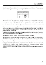
Improper wiring is one of the two major causes of installation problems. Care must be taken in 
following the cable or connector colors table, shielding, tightening of connector screws, short 
circuits, etc.  
 

Summary of Contents for iQ Zone

Page 1: ...Installation Manual...

Page 2: ......

Page 3: ...cons 22 9 2 2 Temperature Set icons 23 9 2 3 Time Schedule Set Points Icons 24 10 ZONING SYSTEM INSTALLATION PROCEDURE 24 10 1 Initial Configuration 24 10 2 Master Zone Control Module Initial Configur...

Page 4: ...er Installation Recommendations 37 14 TEMPERATURE SENSOR SONDAREMOTAI 38 14 1 Functional Description 38 14 2 Component description 38 14 3 Connection instructions 38 15 Table 1 Installer Parameters 39...

Page 5: ......

Page 6: ...Do not ever dispose of this equipment with household waste Electrical and electronic products contain substances that can be harmful to the environment if they are not given proper treatment The symbo...

Page 7: ...re sensors A variety of dampers styles are available to be use with round or rectangular duct systems 3 1 Airzone Controller The Airzone Controller is the main component of the zoning system The contr...

Page 8: ...ation error with the thermostat or an operation failure with the associated damper motor it will send an error message to the Airzone Controller which in turn will relay it to the iQ Controller 3 3 To...

Page 9: ...l Module while Zone Control Modules that will follow a given Master Controller will have addresses ranging from 9 through 32 Those Zone Control Modules are called Subordinate Zone Control Modules Whil...

Page 10: ...s for wiring All wires that will end in a connector should be prepared as shown below Fig 1 If the cable will end inside the thermostat base then this is the recommendation to prepare the cable Fig 2...

Page 11: ...at cable will be connected together and isolated Do not connect the shield to the Zone Control Module Connector The cable that connects the thermostat with the Zone Control Module should not exceed 45...

Page 12: ...figured and there are no errors detected the installer must press this button to save the configuration table in the Airzone Controller The button must be kept pressed while the IQ Bus Activity Config...

Page 13: ...uct using the supplied grommet and being sure that the tip of the probe is exposed to the airflow The Airzone Controller has a micro switch bank that must be set for normal operation Only one switch h...

Page 14: ...mmunicating with the iQ Controller During the process of saving the configuration setup the LEDs will be ON while receiving information from the Zone Control modules and will return to OFF once the co...

Page 15: ...Fig Twist the strands insert the stripped ends into the corresponding connector terminal and tighten the screws until fixed 7 POWER SUPPLY 7 1 Functional Description The universal auto detection powe...

Page 16: ...The internal fuse protects the unit and is not user replaceable In the event of an internal failure the unit must be returned to the manufacturer 8 ZONE CONTROL MODULE 8 1 Installing the Zone control...

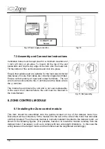
Page 17: ...17 Fig 12 Fig 13 Fig 14...

Page 18: ...e It has to supply NO or NC dry contacts Door Contact Input Same as before this is a dry contact connector If the user wants to use a Window or Door Contact the device can be purchase in a hardware st...

Page 19: ...parameter This value goes from 10 to 100 and represents the proportion of CFM that the zone is using related to the maximum nominal CFM supplied by the AHU This parameter will not be available in Subo...

Page 20: ...ter value St OFSt Offset This parameter allows the Installer to adjust the zone temperature reading and display in a range from 5 F to 5 F The following are read only parameters that allow the service...

Page 21: ...f three parts base cover and touch screen Follow these steps for correct installation and wiring 1 Attach the base to the wall with two screws passing the communication bus wires through the circular...

Page 22: ...ints 9 2 Icon Description It is very important to be familiar to the icons in the thermostat not only for installation process but also to understand and support the end user on service calls Followin...

Page 23: ...Automatic Mode and there is not a program set up for the current time and day the thermostat will go automatically to OFF mode and will stay there until the mode is set to Manual Hour Display In norma...

Page 24: ...d install the thermostats on them All thermostats should show the start up screen indicating that the initial setup should be executed As a general guideline keep in mind that a blinking value for a p...

Page 25: ...After setting the Zone control module parameter to MASTER the screen will appear as follows The second parameter will request the installer to assign to the Zone control module its network address ZC...

Page 26: ...F mode exiting from the initial set up mode Upon entering this parameter the thermostat will go to OFF mode Be sure to power it on again before proceeding to configure the next Zone control module 10...

Page 27: ...esses of the Subordinate Zones can be any number between 09 and 32 They do not need to be sequential The installer can choose any address of his her choice Upon entering this parameter the thermostat...

Page 28: ...nter into the Installer s Parameters area A second push and hold of the Airzone icon will make the Zone control module enter into the Installer parameters mode and the first parameter ZCon will appear...

Page 29: ...on This will put the thermostat in the OFF mode Touch the ON OFF icon again to turn it back to ON which is the normal operation mode 11 2 4 Resetting a Zone Control Module If on the initial power ON t...

Page 30: ...D13 and D14 will light up Continue pressing the button until both LEDs turn off The Airzone Controller is now ready to be connected to the iQ Controller 12 DAMPERS INSTALLATION Dampers must be install...

Page 31: ...rubber foam to seal the installation and a motor Fig 3 Retrofit round damper 12 1 3 Assembly and Connection Instructions Follow this procedure to install the Retrofit Round Damper 1 Align the cut out...

Page 32: ...stem 13 2 Component Description Fig 6 Round Motorized Damper 13 2 1 Assembly and Connection Instructions If the damper is mounted horizontally it is recommended that the motor stay on the side of the...

Page 33: ...lexible Duct 13 3 Rectangular motorized damper retrofit RMDR 13 3 1 Functional Description This product is designed to be inserted in a rectangular duct 13 3 2 Component Description This damper is des...

Page 34: ...talling the damper connect the motor cable to the zone module Although the damper has been specifically designed to be used in metal ducts it can be installed in fiber board ducts but the installer wi...

Page 35: ...s Dampers Airzone has two types of bypass dampers to be used depending on the installation They are free release bypass dampers and ducted bypass dampers The following requirements must be satisfied f...

Page 36: ...Incorrect connection of the bypass duct to the return duct Airzone has two types of free release bypass dampers rectangular and circular the latter is characterized by the fact that it can be used in...

Page 37: ...21 Circular Bypass Damper 13 4 3 Bypass Damper Installation Recommendations The following recommendations should be followed for correct operation of the bypass damper 1 Since bypass dampers are dire...

Page 38: ...the same precautions described for the zone thermostat Fig 13 through 16 14 2 Component description The remote temperature sensor must be connected to the Master Zone Control Module in the connector...

Page 39: ...ZCPC Zone control module Remote Temperature Sensor Only for Master Zone control modules ON OFF ZCSI Zone control module Motion Detector Input Only for Master Zone control modules OFF NC NO ZCRI Zone c...

Page 40: ...the configuration of the parameter Err 6 Zone control sensor short circuit Check that the circuit of the sensor connected to the zone control if any has not shorted out Check the configuration of the...

Page 41: ...lowed Those cases indicated by WSC are based in an installation including 32 Zone modules Maximum distances will depend on the number of modules needed If distances longer than those in the table are...

Page 42: ...wer connector is included with the power supply There are clear identifications in the power supply for voltage in and out and polarity Please follow them carefully The power supply also includes a DI...

Page 43: ......

Page 44: ......

Page 45: ......

Page 46: ...http www airzoneusa com http www nortekhvac com O Fallon MO 666D 0612 Printed in U S A 06 12 iQ Zone is a trademark of Nortek Global HVAC LLC Nortek Global HVAC LLC 2015 All Rights Reserved...

Reviews: