


7
2. ZONING SYSTEM OVERVIEW
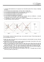
The iQ Zoning system has been designed to support a maximum of 8 zones, with a maximum of
32 Dampers. Each zone, will have an associated Thermostat. Zones and Dampers can be
associated in any combination from 1:1 to 1:24.
3. COMPONENTS OVERVIEW
The Zoning System is composed by three main electronic components and a number of
mechanical components like supply dampers and a bypass damper, depending on the
installation.
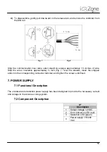
The electronic components are:
1) Airzone Controller
2) Zone Control Module
3) Touch Thermostat
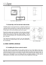
Each system will have (1) Airzone Controller, (1) Zone Control Module for each motorized
damper, (1) Touch Thermostat for each Zone, and (1) power supply.
The system may also be set up with remote zone temperature sensors. A variety of dampers
styles are available to be use with round or rectangular duct systems.
3.1 Airzone Controller
The Airzone Controller is the main component of the zoning system. The controller is also the
interface between the zoning system and the iQ Controller.
This component performs the following functions:
1) gathers information from the Zone Control Modules
2) determine the heating and cooling capacity demand
3) determine zone ventilation requirements
4) manage the opening and closing of the zone dampers.
The Airzone Controller will also provide all the information required by the iQ Controller to
control the circulating air blower and the Heating and Cooling equipment to operate at its
highest possible performance.
If the Airzone Controller detects a communication problem with any of its components, it will
relay the information to the iQ Controller, which will show the information in the appropriate
screen.
Summary of Contents for iQ Zone
Page 1: ...Installation Manual...
Page 2: ......
Page 5: ......
Page 17: ...17 Fig 12 Fig 13 Fig 14...
Page 43: ......
Page 44: ......
Page 45: ......