


16
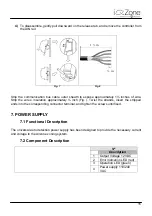
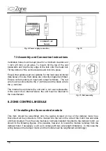
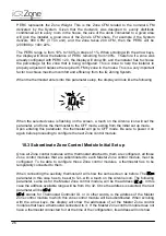
Fig. 9- Power supply connection
Fig. 10
7.3 Assembly and Connection Instructions
Ventilation holes must be kept clear for a minimum clearance of
1 inch (25 mm) on all sides. To mount, tilt the top of the unit
backwards and clip the top edge of the lock onto the metal rail.
Tilt the bottom of the unit backwards and click into place.
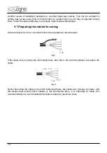
Ensure that cables used are suitable for the load (see technical
data below). Ensure that cables are correctly stripped and fitted.
Ensure correct polarity at input and output terminals. The red
wire must be connected to the (+) terminal and the black wire to
the (-) terminal.
The internal fuse protects the unit and is not user-replaceable.
In the event of an internal failure, the unit must be returned to
the manufacturer.
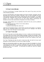
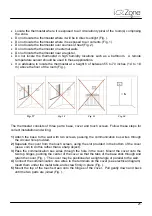
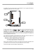
8. ZONE CONTROL MODULE
8.1 Installing the Zone control module
This item should be assembled onto the guides located on top of the damper motor box.
Disconnect all the connectors, fit the module into the rail on the side of the motor box and slide
until fully inserted. Thus the zone module is normally installed mounted to the damper motor, as
shown in the following figures. (It is possible, however, to locate the module remotely from the
damper motor if necessary, such as to comply with bus wire length limitations. In this case the
wiring between the damper motor and the module must be lengthened accordingly.):
Fig. 11- Rail assembly
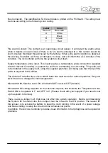
110/240 VAC
Source
Summary of Contents for iQ Zone
Page 1: ...Installation Manual...
Page 2: ......
Page 5: ......
Page 17: ...17 Fig 12 Fig 13 Fig 14...
Page 43: ......
Page 44: ......
Page 45: ......