


22
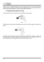
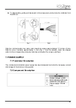
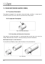
Fig. 21
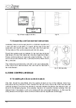
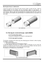
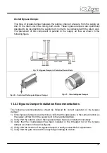
Fig. 22
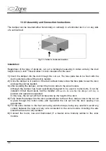
Fig. 23
NOTE
: Take care when connecting the wires so that strands do not come into contact
with other terminals or with the circuit board of the touch screen. Be sure the cable shield
and ground wire are left outside the thermostat base so they do not contact the circuit
board of the touch screen.
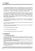
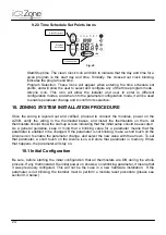
Please, refer to the User Manual to learn the use of the User Settings and how to define the
Time Scheduled Set Points
9.2 Icon Description
It is very important to be familiar to the icons in the thermostat, not only for installation
process but also to understand and support the end user, on service calls.
Following are shown the thermostat icons related to a given functionality, for simplicity
reasons.
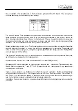
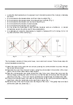
9.2.1 Normal Display Icons
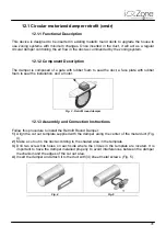
Fig. 24
AC Mode: The AC mode is set in the IQ Thermostat. When the temperature display is
touched the Mode Icon will flash for 5 seconds.
Base
Cover
Touch
Screen
AC Mode
indication:
Stop
Ventilation
Cool
Heat
Day of the week
Temperature Units
Hour display
Manual Mode
Automatic Mode
Temperature Display
ON/OFF icon
Summary of Contents for iQ Zone
Page 1: ...Installation Manual...
Page 2: ......
Page 5: ......
Page 17: ...17 Fig 12 Fig 13 Fig 14...
Page 43: ......
Page 44: ......
Page 45: ......