


65
10-26. Automatic Address Setting
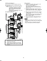
10-26-1. Basic wiring diagram
●
Link wiring
NOTE
●
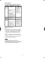
A terminal plug (black) is attached to each of the outdoor unit
control PCBs. At only 1 outdoor unit, leave the terminal plug
short-circuit socket on the “Yes” side. At all the other outdoor
units, change the socket (from “Yes” to “No”).
●
A maximum of 8 indoor units can be connected to 1 remote
controller for group control.
3-1
3-2
3-3
1-1
1-2
1-3
2-1
2-2
1
2
3
Inter-unit control
wiring
(Change setting to “1”)
System address 1
No. 1
Remote controller communication
wiring for group control
Terminal plate 1, 2
Terminal plate 1, 2
Outdoor unit
Indoor unit
Wireless remote
controller
Wired remote
controller
Wireld remote
controller
Inter-unit control wiring
Remote controller communication
wiring for group control
No. 2
No. 3
(Change setting to “2”)
System address 2
(Change setting to “3”)
System address 3
Change the terminal
plug (black) short-
circuit socket
Change the terminal
plug (black) short-
circuit socket
* If wall-mounted type units are used for a simultaneous-
operation multi system (group control), refer to 10-16.
System Control (basic wiring diagrams and wiring
procedures) when wiring.
Fig. 10-23
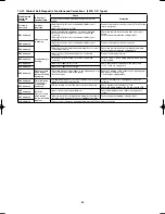
10-26-2. Setting the outdoor unit system addresses
For basic wiring diagram (Set the system addresses: 1, 2, 3...)
ON
1
2
Outdoor unit control PCB
DIP switch
System address
System address rotary switch
(Set to “0” at time of shipment)
System address rotary switch
10s
20s
ON
OFF
3 – 6 HP
Fig. 10-24
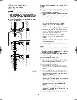
System address
No.
System address
10s digit
(2P DIP switch)
System address
1s place
(Rotary switch)
0 Automatic address
(Setting at shipment = “0”)
Both OFF
ON
1
2
ON
OFF
“0” setting
1 (If outdoor unit is No. 1)
Both OFF
ON
1
2
ON
OFF
“1” setting
2 (If outdoor unit is No. 2)
Both OFF
ON
1
2
ON
OFF
“2” setting
11 (If outdoor unit is No. 11)
10s digit ON
ON
1
2
ON
OFF
“1” setting
21 (If outdoor unit is No. 21)
20s digit ON
ON
1
2
ON
OFF
“1” setting
30 (If outdoor unit is No. 30)
10s digit and 20s
digit ON
ON
OFF
ON
1
2
“0” setting
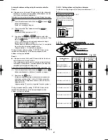
System address rotary switch
System address 10s digit and 20s digit
DIP switch
Automatic address
button (black)
Terminal plug (black)
3 – 6 HP
System address rotary switch
System address 10s digit and 20s digit
DIP switch
Automatic address
button (black)
Terminal plug (black)
3 – 6 HP
Airwell̲PAC-i̲eng.indb 65
Airwell̲PAC-i̲eng.indb 65
2009/07/09 16:13:45
2009/07/09 16:13:45
Summary of Contents for OU-PSINV-25HR
Page 75: ...75 ...


