


16
3. How to Install the Indoor Unit
■
4-Way Air Discharge Semi-Concealed Type
(4WK Type)
3-1. Preparation for Ceiling Suspension
This unit uses a drain pump. Use a carpenter’s level to check
that the unit is level.
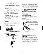
3-2. Mounting the Suspension Bolts
(1) Fix the suspension bolts securely to the ceiling using the
method shown in the diagrams (Figs. 3-1 and 3-2), by
attaching them to the ceiling support structure, or by any
other method that ensures that the unit will be securely and
safely suspended.
(2) Follow Fig. 3-2 and Table 3-1 to make the holes in the
ceiling.
Insert
Hole-in-anchor
Hole-in-plug
Concrete
Suspension bolt (M10 or 3/8")
(field supply)
Fig. 3-1
Unit: mm
B (suspension bolt pitch)
D (ceiling opening dimension)
C (ceiling opening dimension)
A (suspension bolt pitch)
Fig. 3-2
Table 3-1
Unit: mm
Length
Type
A
B
C
D
12, 16, 18, 25, 36, 48, 60
788
723
885
885
(3) Determine the pitch of the suspension bolts using the
supplied full-scale installation diagram. The diagram
and table (Fig. 3-3 and Table 3-2) show the relationship
between the positions of the suspension fitting, the unit,
and the panel.
E
A B
C
D
35
Unit: mm
Drain outlet
(other side) (VP25)
Refrigerant tubing joint
(narrow side)
Refrigerant tubing joint
(wide side)
Suspension lug
Fig. 3-3
Table 3-2
Unit: mm
Length
Type
A
B
C
D
E
12, 16, 18, 25
113
173
256
210
88
36, 48, 60
113
173
319
210
88
3-3. Placing the Unit Inside the Ceiling
(1) When placing the unit inside the ceiling, determine the
pitch of the suspension bolts using the supplied full-scale
installation diagram. (Fig. 3-4)
Tubing and wiring must be laid inside the ceiling when
suspending the unit. If the ceiling is already constructed,
lay the tubing and wiring into position for connection to the
unit before placing the unit inside the ceiling.
(2) The length of suspension bolts must be appropriate for a
distance between the bottom of the bolt and the bottom of
the unit of more than 15 mm. (Fig. 3-4)
Over 15 mm
12 – 17 mm
Full-scale installation diagram
(printed on top of container box)
Supplied bolt
Fig. 3-4
Airwell̲PAC-i̲eng.indb 16
Airwell̲PAC-i̲eng.indb 16
2009/07/09 16:13:21
2009/07/09 16:13:21
Summary of Contents for OU-PSINV-25HR
Page 75: ...75 ...


