506878-01
Page 55 of 62
Issue 1139
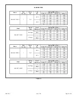
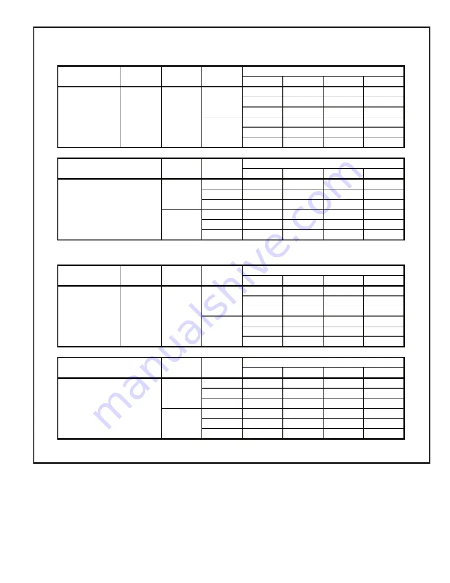
BLOWER DATA
Setting "D"
Setting "C"
Setting "B"
Setting "A"
1560
1760
1905
2080
1415
1610
1740
1930
1285
1485
1560
1745
1155
1325
1420
1565
1055
1200
1310
1480
935
1075
1170
1315
Setting "D"
Setting "C"
Setting "B"
Setting "A"
+
1310
1560
1745
1955
Norm
1220
1405
1570
1795
-
1075
1270
1430
1635
+
935
1065
1245
1405
Norm
865
970
1145
1280
-
790
890
1025
1165
Setting "D"
Setting "C"
Setting "B"
Setting "A"
1650
1845
2000
2195
1495
1660
1880
1985
1360
1500
1670
1850
1300
1435
1630
1715
1190
1325
1465
1620
1095
1190
1340
1430
Setting "D"
Setting "C"
Setting "B"
Setting "A"
+
1395
1640
1840
2055
Norm
1290
1480
1660
1905
-
1170
1330
1500
1705
+
1015
1160
1330
1480
Norm
940
1085
1200
1345
-
870
965
1110
1225
Model
Cooling
Stage
Speed
Adjustment
Cooling CFM @ .50 w.c.
A95UH2V135C20S
2nd Stage
1st Stage
Model
Motor
Size (hp)
Blower
Size
Temp
Rise
Heating CFM @ .50 w.c.
A95UH2V135D20S
1
11x11
55-85
40-70
Model
Cooling
Stage
Speed
Adjustment
Cooling CFM @ .50 w.c.
A95UH2V110C20S
2nd Stage
1st Stage
Model
Motor
Size (hp)
Blower
Size
Temp
Rise
Heating CFM @ .50 w.c.
A95UH2V110C20S
1
11x11
45-75
35-65
Table 18
Summary of Contents for 95G2UHV
Page 3: ...506878 01 Page 3 of 62 Issue 1139 EXPANDED VIEW Figure 1 ...
Page 28: ...506878 01 Page 28 of 62 Issue 1139 Figure 31 FIELD SUPPLIED WALL TERMINATION ...
Page 29: ...506878 01 Page 29 of 62 Issue 1139 Figure 32 ...
Page 35: ...506878 01 Page 35 of 62 Issue 1139 Figure 47 TRAP DRAIN ASSEMBLY USING 1 2 PVC or 3 4 PVC ...
Page 46: ...506878 01 Page 46 of 62 Issue 1139 TYPICAL WIRING DIAGRAM Figure 56 ...
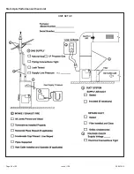
Page 60: ...506878 01 Page 60 of 62 Issue 1139 Start Up Performance Check List UNIT SET UP ...
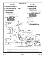
Page 61: ...506878 01 Page 61 of 62 Issue 1139 UNIT OPERATION Heating Mode Cooling Mode ...


