506878-01
Page 54 of 62
Issue 1139
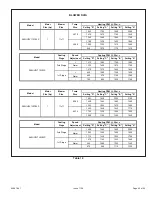
BLOWER DATA
Setting "D"
Setting "C"
Setting "B"
Setting "A"
1450
1565
1725
1865
1310
1450
1585
1690
1155
1305
1450
1545
1120
1265
1420
1520
965
1120
1285
1395
865
950
1120
1235
Setting "D"
Setting "C"
Setting "B"
Setting "A"
+
1385
1595
1820
2020
Norm
1225
1465
1645
1885
-
1065
1320
1504
1675
+
935
1055
1275
1465
Norm
835
980
1120
1335
-
740
870
1010
1150
Setting "D"
Setting "C"
Setting "B"
Setting "A"
1210
1275
1385
1620
1100
1160
1255
1455
1015
1055
1135
1335
1210
1275
1385
1620
1100
1160
1255
1455
1015
1055
1135
1335
Setting "D"
Setting "C"
Setting "B"
Setting "A"
+
1100
1325
1530
1760
Norm
1025
1205
1405
1565
-
920
1080
1260
1440
+
810
980
1085
1235
Norm
760
875
1010
1135
-
695
805
905
1040
A95UH2V110C16S
2nd Stage
1st Stage
Temp
Rise
Heating CFM @ .50 w.c.
A95UH2V110C16S
3/4
11x11
60-90
35-65
A95UH2V090C20S
2nd Stage
1st Stage
Model
Motor
Size (hp)
Blower
Size
Model
Cooling
Stage
Speed
Adjustment
Cooling CFM @ .50 w.c.
Model
Cooling
Stage
Speed
Adjustment
Cooling CFM @ .50 w.c.
Model
Motor
Size (hp)
Blower
Size
Temp
Rise
Heating CFM @ .50 w.c.
A95UH2V090C20S
1
11x11
40-70
30-60
Table 17
Summary of Contents for 95G2UHV
Page 3: ...506878 01 Page 3 of 62 Issue 1139 EXPANDED VIEW Figure 1 ...
Page 28: ...506878 01 Page 28 of 62 Issue 1139 Figure 31 FIELD SUPPLIED WALL TERMINATION ...
Page 29: ...506878 01 Page 29 of 62 Issue 1139 Figure 32 ...
Page 35: ...506878 01 Page 35 of 62 Issue 1139 Figure 47 TRAP DRAIN ASSEMBLY USING 1 2 PVC or 3 4 PVC ...
Page 46: ...506878 01 Page 46 of 62 Issue 1139 TYPICAL WIRING DIAGRAM Figure 56 ...
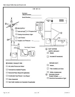
Page 60: ...506878 01 Page 60 of 62 Issue 1139 Start Up Performance Check List UNIT SET UP ...
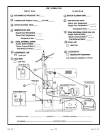
Page 61: ...506878 01 Page 61 of 62 Issue 1139 UNIT OPERATION Heating Mode Cooling Mode ...


