©
A
ir
B
orne
W
ind
S
ports
P
ty.
L
td.
XT 582 Maintenance Manual
Issue 1.0
September 21st 2005
Page 9
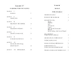
LIST OF TABLES
Table 1 XT 582 Data Package............................................................................................................... 2
Table 2 Amendment Record Sheet........................................................................................................ 3
Table 3 Log Of All Effective Pages, Issue 1 ........................................................................................... 4
Table 4 Imperial / Metric Conversions.................................................................................................... 7
Table 5 Initial Assembly Procedure (GJP144) ..................................................................................... 11
Table 6 Airframe Limitations ................................................................................................................ 15
Table 7 Time Limits of Components .................................................................................................... 16
Table 8 Propeller and Gearbox Maintenance Schedule ....................................................................... 18
Table 9 Engine Maintenance Schedule ............................................................................................... 20
Table 10 Trike Base and Landing Gear Maintenance Schedule .......................................................... 21
Table 12 Torque Table ........................................................................................................................ 43
Table 13 Excerpt from GJP 141, Complete List of Tie Wire locations .................................................. 44
Table 14 Fuel Tank Schematic ............................................................................................................ 51
Table 15 SkyDAT Monitored Operations.............................................................................................. 91
LIST OF FIGURES
Figure 1 Main structural members ....................................................................................................... 12
Figure 2 Cockpit (XT 912 shown in photo) ........................................................................................... 12
Figure 3 Under-seat bags .................................................................................................................... 13
Figure 4 Mast Block Area (XT 912 shown in photo) ............................................................................. 13
Figure 5 Steering and foot levers ......................................................................................................... 14
Figure 6 Power plant............................................................................................................................ 14
Figure 7 Front Mast to Mast Brace Check............................................................................................ 22
Figure 8 Major Dimensions (XT912 Shown) ........................................................................................ 24
Figure 9 Tie Down Hook Location........................................................................................................ 28
Figure 10 Front wheel with tie downs................................................................................................... 28
Figure 11 Tie on Rear Wheel............................................................................................................... 29
Figure 12 Trike on Trailer .................................................................................................................... 29
Figure 13 Parking of Trike (Upwind Wing Down) ................................................................................. 30
Figure 14 Securing of Base Bar With Bungee...................................................................................... 30
Figure 15 Parking Trike Tail to the Wind .............................................................................................. 31
Figure 16 Fuel Specifications............................................................................................................... 33
Figure 17 Air filter protection during cleaning....................................................................................... 37
Figure 18 Seat Mast Block Sub Assembly ........................................................................................... 40
Figure 19 Outside Nut with spat bracket .............................................................................................. 41
Figure 20 Inside Nut and Inner Spat Bracket ....................................................................................... 41
Figure 21 View of Locking Bolt head.................................................................................................... 41
Figure 22 Tie Wires on Propeller ......................................................................................................... 44
Figure 23 Rear Wheels Special Safetying............................................................................................ 44
Figure 24 Muffler Safety Wire and Springs .......................................................................................... 45
Figure 25 Mast Top Safetying.............................................................................................................. 45
Figure 26 Finger Filter, as installed, as well as the unit prior installation. ............................................. 53
Figure 27 Fuel Line Check Example .................................................................................................... 54
Figure 28 Fuel Flow Sender Device..................................................................................................... 55
Figure 29 Fuel Sender and tools.......................................................................................................... 56
Figure 30 Fuel Tap Bracket Sub Assembly.......................................................................................... 57
Figure 31 SkyDAT Console Photo ....................................................................................................... 58
Figure 32 Features of the Instrumentation ........................................................................................... 58
Figure 33 Rear Shock Dimension Check ............................................................................................. 61
Figure 34 Front Shock Set up .............................................................................................................. 62
Figure 35 Steering Damper Setting, (Dwg # 5610). ............................................................................. 62