©
A
ir
B
orne
W
ind
S
ports
P
ty.
L
td.
XT 582 Maintenance Manual
Issue 1.0
September 21st 2005
Page 76
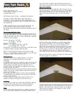
61.20.50 Place the pre assembled propeller onto the engines mount
Carefully grip the two Hub Blocks together with your hands and lift from the ground to the engines
propeller mount. The M8 Bolts will match the Engines mount pattern. Mate the bolts to the holes while
ensuring that the propellers or bolts don’t fall. While still holding everything in place finger tighten the
bolts in sequence (See the Sequencing in the torquing section). The Propeller should now hold itself in
place. The photo depicts installation of a 912 propeller. The procedure is the same except that the
engine plate on the 582 does not have dowels as shown on photo. Put the M8 full nyloc nuts on, but do
not tighten untill last. If they are not assembled at this stage they will be impossible to get on after the
bolts have been torqued.
Figure 49 Mounting the Propeller
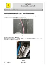
61.20.60 Nip the AN4 Bolts to allow pitch adjustment
Tighten the AN4 Nuts in sequence in order that the propellers can still be easily rotated by hand, but
are in a positively held condition, so that they may be adjusted both easily and precisely. Evenly tighten
the bolts / nuts in a sequence < bolt 1 – bolt 4 – bolt 2 – bolt 5 – bolt 6 – bolt 3>. Apply the torque to the
nuts – not the bolts. Wait until after the Propeller has been adjusted to fully torque either sets of bolts.
Figure 50 Propeller AN4 Bolt Tightening Sequence Numbers
CAUTION
PULL THE BLADE RADIALLY OUTWARDS TO SEAT THE BLADE INTO IT’S HUB BLOCK
LOCATION WHILE TIGHTENING THE AN4 NUTS/BOLTS, THIS ENSURES UNIFORM
DIAMETRICAL POSITIONING OF THE BLADES RELATIVE TO THE HUB AND EACH OTHER.