


10
Chapter 2. Hardware Setup
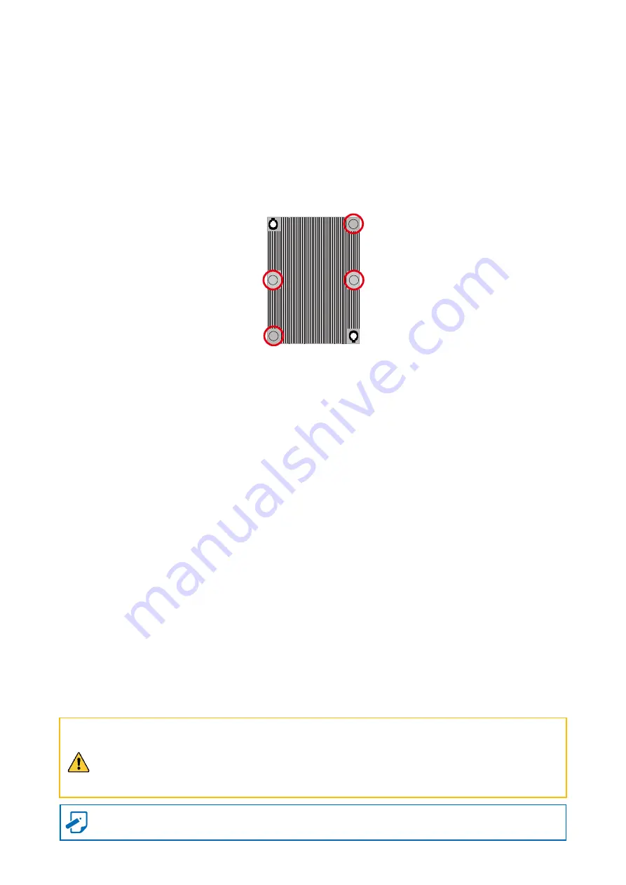
PHM Screw Installation Order:
The PHM sits level with the processor socket assembly. The PHM is NOT installed properly
if it does not sit level with the processor socket assembly. Once the PHM is seated over
the processor socket assembly, the four heat sink torque screws must be secured in the
following order as shown below.
Processor Heat Sink – Top View with Screw Tightening Order
CAUTION
Failure to tighten the heat sink screws in the specified order may cause damage to the
processor socket assembly. Heat sink screws should be tighted to 12 in-lbs torque
according to the ndicated order on the top of the heat sink label.
This information is provided for professional technicians only.
Summary of Contents for SB401-VG
Page 1: ...UM_SB401 VG_v1 2_081921 SB401 VG Storage Barebone User s Manual...
Page 12: ...3 Chapter 1 Product Features 1 3 System Block Diagram...
Page 49: ...40 Chapter 3 Hardware Settings 3 3 1 Placement Top view Backside view 3 3 HDD Backplane 24 Bay...
Page 74: ...65 Chapter 5 BMC Configuration Settings Step 2 Input the IP address Set static IP...
Page 75: ...66 Chapter 5 BMC Configuration Settings Step 3 Input the subnet mask address...