BE-BX42S / BE-WC62G USER MANUAL
25
MOUNTING & UNHOOKING TRACTOR (CONT.)
BE-BX42S / BE-WC62G
Leveling Adjustments
1. Slowly raise the machine through its working range
to make sure telescoping portion of the PTO shaft
doesn't bottom out.
2. Level the machine front & rear and side to side using
the jack screw on the right arm and the turnbuckle on
the top link.
NOTE
- The chipper should always be level on the
ground in its working position.
3. To unhook from the tractor, reverse the above
procedure. Always perk the machine in a dry level area.
If vandalism is a problem, remove the PTO driveline
and store in a secure place.
Fig. 19
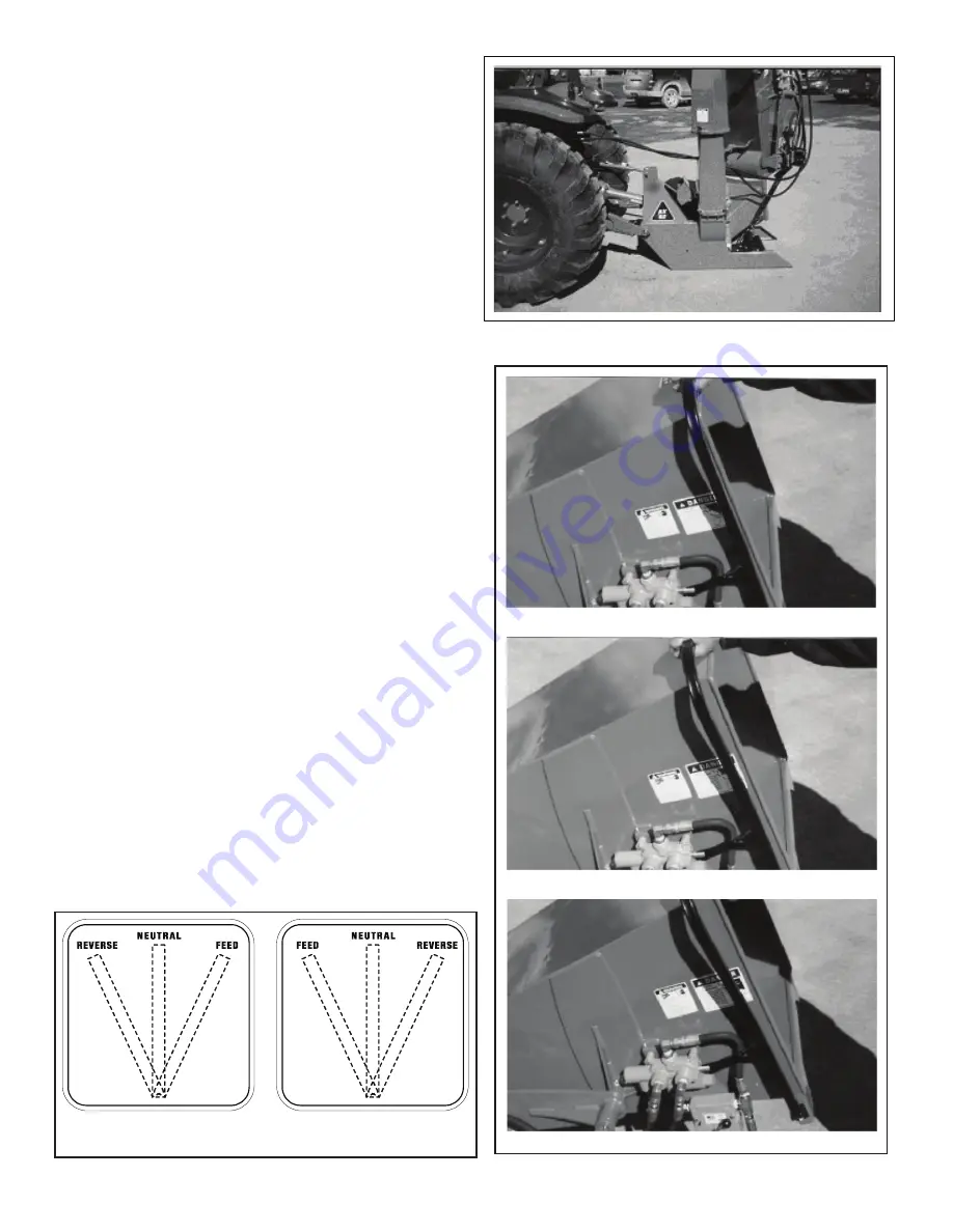
Connect the hydraulics
1. Use a clean rag or paper towel to clean the dirt
from couplers on the hose ends and the tractor.
2. Connect the hoses to the tractor couplers.
Be sure the couplers are securely seated.
3. Route and secure the hoses along the hitch
with clips, tape or plastic ties to prevent
binding and pinching. Be sure to provide
slack for turning.
NOTE
- Always connect to the hydraulic circuit
with a detent.
Fig. 18
WARNING
HIGH PRESSURE FLUID HAZARD
To prevent serious injury or death from
high pressure fluid:
• relieve pressure on system before
repairing or adjusting.
• Wear proper hand and eye protection
when searching for leaks. Use wood
or cardboard instead of hands.
• Keep all components in good repair.
Z9400
Leveling Adjustments
1. Slowly raise the machine through its working
range to make sure telescoping portion of the
PTO shaft doesn’t bottom out.
2. Level the machine front & rear and side to side
using the jack screw on the right arm and the
turnbuckle on the top link.
NOTE
- The chipper should always be level on
the ground in its working position.
3. To unhook from the tractor, reverse the above
procedure. Always perk the machine in a dry
level area.
If vandalism is a problem, remove the PTO
driveline and store in a secure place.
CONTROLS
All controls are conveniently positioned next to
where the operator would stand when feeding the
machine to provide easy operation. Review this
section to familiarize yourself with the location and
function of each control before starting.
Hydraulic Feed Control Lever:
This lever is positioned to extend around the feed
hopper and provides access from all sides. It is only
available when the chipper is equipped with the
optional hydraulic feed hopper.
Pull the control all the way out to engage the
feeding system. Push it in slightly to the first detent
to stop the feeding system. Push the control all the
way in to reverse the feeding system.
NOTE
- Use the typical flow divider next to the
control valve to set the feeding spread.
CONTROLS
BE-BX42S / BE-WC62G
Z940
Z940
Z940
Z940 4444
Z940
Z940
Z940
Z940
Feeding
Neutral/Stop
Reversing
Left Side
Right Side
Control Schematic
Fig. 20
All controls are conveniently positioned next to where
the operator would stand when feeding the machine
to provide easy operation. Review this section to
familiarize yourself with the location and function
of each control before starting.
Hydraulic Feed Control Lever:
This lever is positioned to extend around the feed hopper
and provides access from all sides. It is only available
when the chipper is equipped with the optional
hydraulic feed hopper.
Pull the control all the way out to engage the feeding
system. Push it in slightly to the first detent to stop
the feeding system. Push the control all the way in to
reverse the feeding system.
NOTE
- Use the typical flow divider next to the control
valve to set the feeding spread.


