


ISTRUZIONI ORIGINALI
TECHNICAL INFORMATION
41/43
87-900-136-01
Float valve cleaning procedure
If the float valve for oil recovery doesn’t operate
well, there could be oil carry out from the dis-
charge port.
To clean the float valve, follow these instructions;
1) Remove the cover (position B2, refer to page
40), unscrewing the screws (position B1, refer
to page 40).
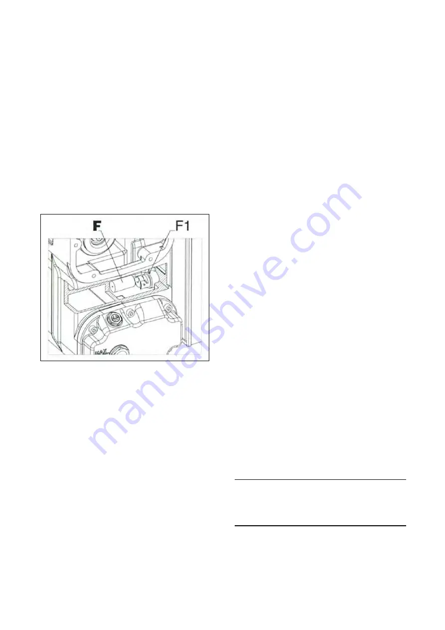
2) Remove the float valve (position F of the follow-
ing figure) from its grub-screw (position F1 of
the following figure).
3) Clean the float valve, and its internal reduction
fitting, with compressed air by blowing the op-
posite direction with respect to the normal oil
flow
4) Fit the float valve in its housing.
5) Fit the discharge cover.
Exhaust filters replacement procedure
Very dirty exhaust filters may cause a considerable
pump temperature increase and in extreme cases
oil lubricant spontaneous ignition.
Maximum allowed pressure in the tank is 0.7 bar
measured at the maximum capacity, when the
pump is working with the inlet open to atmospheric
pressure.
If a pressure gauge has been fitted on the tank,
check the exhaust filter blockage with the pump
warm.
To replace the filter apply the following instruc-
tions;
1) Remove the cover (position B2, refer to page
40) by unscrewing its screws (position B1, refer
to page 40).
2) Unscrew the screw (position B4, refer to page
40), remove the washer (position B5-B6, refer
to page 40) and then the fixing cartridge disk
(position B7, refer to page 40), the washer and
tighten the screws.
3) Re-assemble the discharge cover. If necessary,
replace the gasket (position B3, refer to page
40).
Oil separator change procedure
If the oil filter is clogged, the oil circulating from the
tank through the pump could be dirt and cause a
severe damage to the pump.
To change the oil filter (position C, refer to page
40), follow these instructions:
1) Be sure that the oil inside the pump has been
completely discharged (for further information
see the “Oil change procedure”);
2) Unscrew the oil filter with by means of a chain
wrench from the oil-tank;
3) Clean the contact surface between the oil tank
and the filter;
4) Screw the oil filter by hands to the oil-tank.
Gas ballast felt disk change procedure
If the gas ballast felt disk is clogged, an insufficient
amount of air flows through the pump and conse-
quently the pump may not discharge the water va-
por properly.
To change the gas ballast felt disk, follow these
instructions:
1) Remove the gas ballast;
2) Unscrew its cap;
3) Remove the upper micro-stretched sheet disk;
4) Substitute the felt disk with a new one;
5) Re-assembly the gas ballast and then screw it
using a new o-ring directly on the Ball valve.
Coupling elastic element replacement proce-
dure
Please refer to figure “Pumps Major Parts” on
page 40.
Remove the motor assembly (position D1, refer to
page 40) unscrewing the screws (position D2, re-
fer to page 40). Check the elastic element (posi-
tion D, refer to page 40) conditions. If necessary,
replace it. Re-assemble by means of the screws.
CAUTION
Use suitable lifting equipment to lift the motor;
−
Motor weight for MS-301: approximately 55 kg
−
Motor weight for MS-631: approximately 190 kg


