


ISTRUZIONI ORIGINALI
TECHNICAL INFORMATION
27/43
87-900-136-01
SECTION III
SERVICING
General information
Before every maintenance operation:
−
Ensure that the pump motor is disconnected from the electrical network so that it can’t automatically start.
−
Make sure the pump has reached an ambient temperature.
−
Introduce air in the inlet port.
In order to keep the pump operating at a high efficiency level, it is mandatory to follow all periodical service
points listed in the table below. However, more frequent service operations may be necessary depending on
what the pump is used for (suction of condensable vapours, suction of powders or polluting substances). For
such cases, only direct experience can indicate the correct service frequency needed. Please contact Varian
Technical Support for further details. The exhausted oil and replaced spare parts must be considered as spe-
cial waste products and handled according to the local regulations in the country of use.
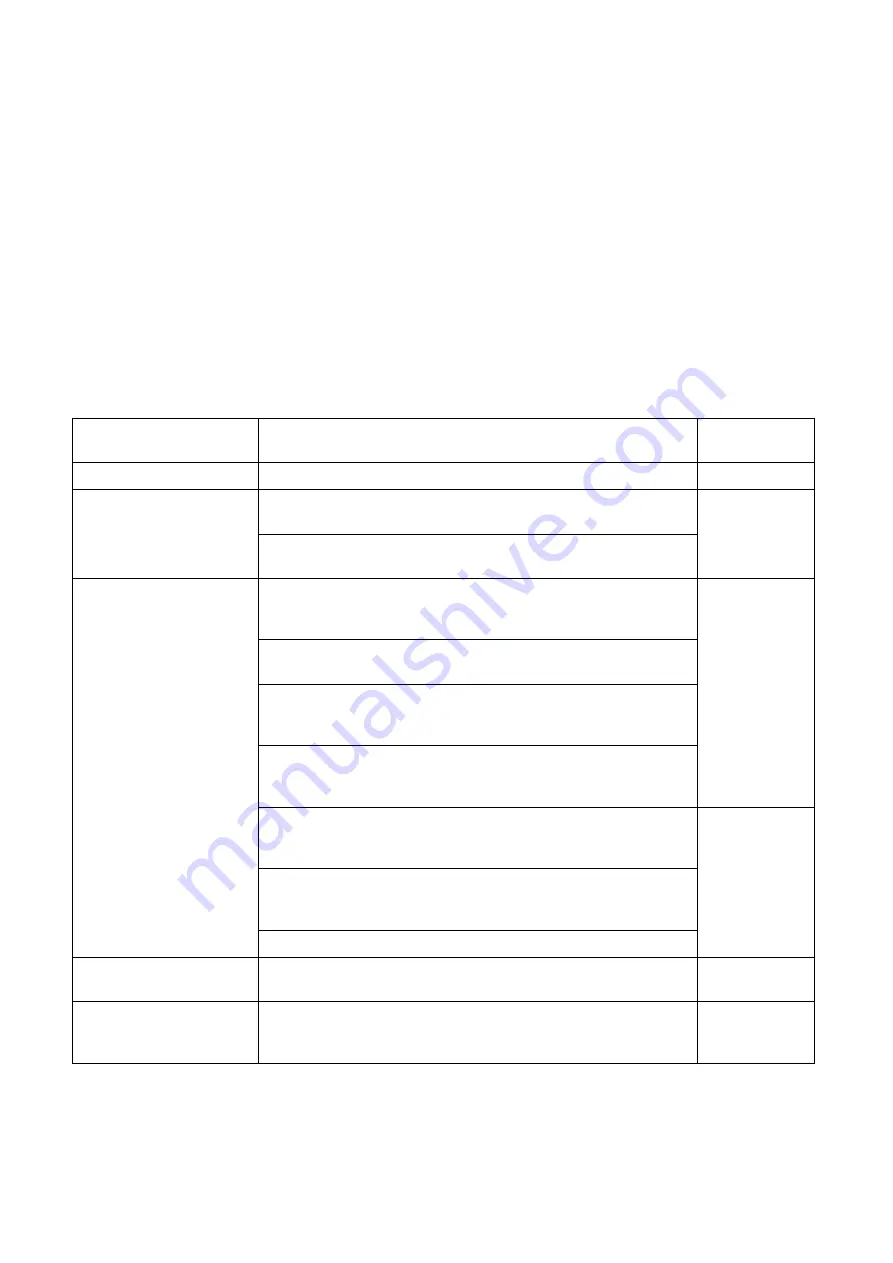
SERVICE FREQUENCY
DESCRIPTION OF THE OPERATION
AUTHORIZED
PERSONNEL
24 hours/every day
Check oil level before starting
Operator
Clean the external inlet element with a blast of air (refer to
“Pumps Major Parts” figure, position A)
100 hours/every week
Clean the cooling surfaces of the pump, of oil cooler and the
electrical motor with a blast of air
Operator
Replace the lubricating oil and oil filter (refer to “Pumps major
parts” figure, position C). Doesn’t use car air filter but with anti
suck back valve. See “Oil change procedure” at page 40
Clean the float valve. See “Float valve cleaning procedure” at
page 41
If the pressure gauge is fitted to the pump, check the oil sepa-
rator (max 0.6 bar); if necessary, replace it. See “Oil separator
change procedure” at page 41
Replace the gas ballast felt disk (refer to “Pumps major parts”
figure, position E. See “Gas ballast felt disk change procedure”
procedure at page 41
Skilled worker
Replace the exhaust filter (refer to “Pumps major parts” figure,
position B). See “Exhaust filters replacement procedure” at
page 41
Check and if necessary replace the coupling elastic insert (refer
to “Pumps major parts” figure, position D). See “Coupling elas-
tic element replacement procedure” procedure at page 41
2000 hours/every 6
months
Check the electrical connections
Skilled worker
8000 hours/every 2
years
Grease the electrical motor bearings
VARIAN
service
30,000 hours/every 5
years
Pump overhaul
VARIAN
service or
Skilled worker
•
The first oil change has to be done after 500 hours of operation. Next oil change must be done within 2000 hours.


