


7-2
Chapter 7
Service
Introduction
Introduction
This chapter contains troubleshooting and repair information. Heed caution signs to avoid damaging the
probe. You may wish to read the
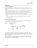
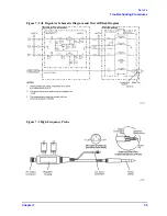
“Theory of Operation” on page 7-3,
with its associated diagrams as an
aid to troubleshooting.
Before You Troubleshoot
Troubleshooting the probe begins with performing the
“Operator’s Check” on page 4-4,
If the probe does not pass the performance tests, refer to the
.
Equipment Required for Troubleshooting
Troubleshooting procedures require the use of a digital multimeter.
Repair Strategy
Probe Tip, Amplifier Microcircuit, and Regulator Assembly
The probe tip and amplifier microcircuit are easily replaced. The regulator assembly (A1) repair can be
performed at either assembly or component level. Module exchange programs are not available for this
product.
Main Cable and Plastic Sleeve Guide
The main cable includes the probe wand, the main cable and the smaller power supply cable. If the cable
is damaged, both the cable and the probe wand assembly must be replaced as a single unit. In this case,
take the following parts off of the old probe for use on the replacement probe:
•
The nose assembly
•
Nut
•
Amplifier microcircuit
These items are shown in
A kit is available that provides a preassembled main cable and probe wand. The wand does not come
with the amplifier microcircuit, nose-assembly, or tip, because these may be easily removed from your
old probe wand. Refer to
for the part number of the kit.
Summary of Contents for 85024A
Page 4: ...iv ...
Page 7: ...1 1 1 General Information ...
Page 13: ...2 1 2 Accessories ...
Page 19: ...3 1 3 Installation ...
Page 24: ...3 6 Chapter3 Installation Returning the Product for Service ...
Page 25: ...4 1 4 Operation ...
Page 30: ...4 6 Chapter4 Operation Operator s Check ...
Page 31: ...5 1 5 Performance Tests ...
Page 40: ...5 10 Chapter5 Performance Tests Average Noise Level ...
Page 41: ...6 1 6 Replaceable Parts ...
Page 46: ...6 6 Chapter6 Replaceable Parts Parts Lists ...
Page 47: ...7 1 7 Service ...
Page 60: ...7 14 Chapter7 Service Replacement Procedure Figure 7 11 Regulator Parts and Wiring ...
Page 64: ...7 18 Chapter7 Service Connector Inspection and Cleaning ...


