


Chapter 7
7-9
Service
Replacement Procedure
Replacing the Amplifier Microcircuit
Tools Required:
10 mm open-end wrench
Small flatblade screwdriver
1. Remove the nose assembly.
2. Remove the amplifier microcircuit.
3. Remove and discard the spring clip and elastic conductive strip.
4. Place the new amplifier microcircuit into the probe heatsink. Place the new elastic conductive strip in
place, making sure the gold traces are facing down and are aligned lengthwise with respect to the
probe. Make sure the elastic strip is flush with the front end of the heatsink. The screwdriver may be
used to move the strip.
5. Place the new spring clip over the elastic strip, flush with the front of the heatsink. The beveled end
of the clip should face away from the amplifier microcircuit. The center of this U-shaped clip must
press into the elastic conductor. Insert one side of the clip into the small slot in the probe heatsink.
Press the other side of the clip down with the small screwdriver until it snaps into the slot on the other
side of the heatsink.
6. Replace the nose assembly and nut.
CAUTION
Failure to remove the nose assembly prior to replacing the tip will result in damage to the
conductive elastomer on the tip assembly.
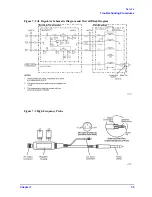
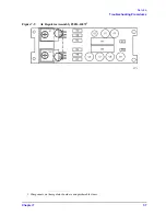
Figure 7-7
Probe Wand Components
Summary of Contents for 85024A
Page 4: ...iv ...
Page 7: ...1 1 1 General Information ...
Page 13: ...2 1 2 Accessories ...
Page 19: ...3 1 3 Installation ...
Page 24: ...3 6 Chapter3 Installation Returning the Product for Service ...
Page 25: ...4 1 4 Operation ...
Page 30: ...4 6 Chapter4 Operation Operator s Check ...
Page 31: ...5 1 5 Performance Tests ...
Page 40: ...5 10 Chapter5 Performance Tests Average Noise Level ...
Page 41: ...6 1 6 Replaceable Parts ...
Page 46: ...6 6 Chapter6 Replaceable Parts Parts Lists ...
Page 47: ...7 1 7 Service ...
Page 60: ...7 14 Chapter7 Service Replacement Procedure Figure 7 11 Regulator Parts and Wiring ...
Page 64: ...7 18 Chapter7 Service Connector Inspection and Cleaning ...


