


Chapter 2
2-5
Accessories
10:1 Divider
10:1 Divider
The 10:1 divider fits over the tip of the probe and provides the following changes to the probe’s
operating parameters:
•
Increases (by a factor of 10) the input voltage at which 1 dB compression occurs.
•
Decreases the input capacitance without changing input resistance, thereby decreasing capacitive
loading.
Two or more dividers may be cascaded to provide higher divide ratios.
Operating Characteristics
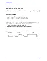
Inspection
Make sure the tip is not bent or discolored. Periodically inspect the barrel of the probe receptacle,
making sure it is clean and free of grit. Clean the receptacle with clean compressed air.
When cascading 10:1 dividers, periodically inspect and clean the exterior of the metal sleeve.
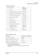
Divider Ratio
10:1
Input Capacitance
Typically <0.7 pF
Input Resistance
1 M
Input Voltage for 1 dB Compression
3.0 Volts Peak
a
a. When used with the active probe.
Maximum Safe DC Input Voltage
200 Volts
Maximum Safe RF Input Voltage
15 Volts Peak
Frequency Range
Same as the active probe (300 kHz to 3 GHz)
Summary of Contents for 85024A
Page 4: ...iv ...
Page 7: ...1 1 1 General Information ...
Page 13: ...2 1 2 Accessories ...
Page 19: ...3 1 3 Installation ...
Page 24: ...3 6 Chapter3 Installation Returning the Product for Service ...
Page 25: ...4 1 4 Operation ...
Page 30: ...4 6 Chapter4 Operation Operator s Check ...
Page 31: ...5 1 5 Performance Tests ...
Page 40: ...5 10 Chapter5 Performance Tests Average Noise Level ...
Page 41: ...6 1 6 Replaceable Parts ...
Page 46: ...6 6 Chapter6 Replaceable Parts Parts Lists ...
Page 47: ...7 1 7 Service ...
Page 60: ...7 14 Chapter7 Service Replacement Procedure Figure 7 11 Regulator Parts and Wiring ...
Page 64: ...7 18 Chapter7 Service Connector Inspection and Cleaning ...


