


7-4
Chapter 7
Service
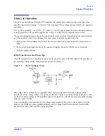
Troubleshooting Procedures
Troubleshooting Procedures
CAUTION
The probe contains an input GaAs amplifier microcircuit that is highly sensitive to
electrostatic discharge (ESD).
When repairing this probe, you must use an anti-static
wrist strap, and work at a station equipped with an anti-static surface!
Before you take a
measurement with a digital multimeter, discharge the leads by touching them to ground.
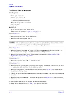
Mechanical Failure of the Protective Sleeve
The probe wand/cable must be replaced if the protective sleeve fails to slide and lock properly.
Electrical Failure of the Probe
Visually Inspect the Probe Tip
Inspect the probe tip for damage. If it is bent or broken, replace it by referring to
. Perform the
“Operator’s Check” on page 4-4
. If the problem persists, perform the
following procedure.
Power Supply Check
Refer to the probe schematic in
when performing the following procedure.
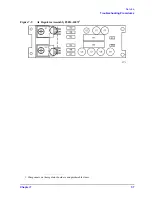
1. Check the probe power output from the supplying instrument or power supply. The output pins and
voltages are shown in
. Check continuity of the ground pin to chassis ground;
it should be less than 1
.
•
If the supplies are within the tolerances given in
“Power Requirements” on page 3-3
continue to
step 2.
•
If the voltage is not present at the supplying device, or the ground pin is open, troubleshoot as
required. Suspect a broken wire going to the probe power jack.
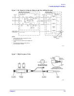
2. Follow the procedure in
“Replacing the Amplifier Microcircuit” on page 7-9,
to remove the probe’s
nose assembly, amplifier microcircuit, elastic conductive strip, and spring clip. These items are
illustrated in
.
Summary of Contents for 85024A
Page 4: ...iv ...
Page 7: ...1 1 1 General Information ...
Page 13: ...2 1 2 Accessories ...
Page 19: ...3 1 3 Installation ...
Page 24: ...3 6 Chapter3 Installation Returning the Product for Service ...
Page 25: ...4 1 4 Operation ...
Page 30: ...4 6 Chapter4 Operation Operator s Check ...
Page 31: ...5 1 5 Performance Tests ...
Page 40: ...5 10 Chapter5 Performance Tests Average Noise Level ...
Page 41: ...6 1 6 Replaceable Parts ...
Page 46: ...6 6 Chapter6 Replaceable Parts Parts Lists ...
Page 47: ...7 1 7 Service ...
Page 60: ...7 14 Chapter7 Service Replacement Procedure Figure 7 11 Regulator Parts and Wiring ...
Page 64: ...7 18 Chapter7 Service Connector Inspection and Cleaning ...


