Ag Leader Technology
DirectCommand Installation
Raven Accu-Flow ISO Kit
Page 14 of 15
February 2015
PN: 2006375 Rev. B
Setting Up
the Display
1. Refer to the Quick Reference Guide, PN: 2006010-ENG, for further
instructions on setting up the Display.
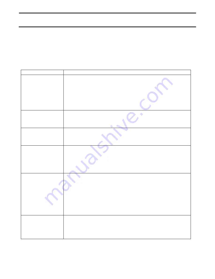
2. The following table describes each of the settings required to create a
configuration. The table on the following page is recommended default
settings based on which control valve is used.
Setting Name
Description
Control Valve
Configuration
Inline Servo:
Rate control is achieved through actuating a control
valve in the solution hose that goes to the booms. When the valve
opens flow increases and when the valve closes, flow decreases.
Bypass Servo
: Rate control is achieved through actuating a control
valve in the return line to the solution tank. When the valve opens, the
flow decreases and when the valve closes the flow increases.
Valve Response 1
Determines the speed of the servo valve when product control error
exceeds the
Response Threshold
setting. Decreasing the value will
cause the servo valve to run slower
Valve Response 2
Determines the speed of the servo valve when product control error is
less than the
Response Threshold
setting. Decreasing the value will
cause the servo valve to run slower.
Allowable Error
Determines the percent of error that is allowed prior to the product
control system making any flow rate corrections.2 % – 3 % is the normal
dead band setting range. Too low of a setting will cause the control
system to continually hunt for the target application rate. Too high of a
setting will cause excessive application error.
Response
Threshold
Determines where the control system switches between using
Valve
response 1 and Valve response 2 speed settings. Decreasing this value
will have the overall effect of speeding up servo valve response.
Increasing this value will have the overall effect of slowing down servo
valve response.
NOTE: Leaving all other valve control settings at the default
value and making a small adjustment to this setting is usually
all that is required to fine-tune the control system.
Flow Meter Cal
This is the number pulses per 10 gallons of product flow thru the Raven
flow meter. The Ag Leader Display requires pulses per gallon for
calibration. To calculate the appropriate values divide the Raven
calibration number by 10 before entering into the Ag Leader Display.


