Ag Leader Technology
DirectCommand Installation
Raven Accu-Flow ISO Kit
Page 12 of 15
February 2015
PN: 2006375 Rev. B
Installing an
Implement
Switch
(Optional)
Parts required for procedure:
(1) Implement Switch
PN: 4001507
(1) Implement Switch Ext. Cable
See Table B
(1) CAN Implement Switch Cable
PN: 4002658
(1) CAN Implement Switch Module
PN: 4002911
Table B
Implement Switch Extensions
Part Number
18 in. Cable
2000453-1
42 in. Cable
2000453-4
10 ft. Cable
2000453-2
25 ft. Cable
2000453-3
NOTE: If using this kit on an implement that is raised out of the ground
when not applying, it is recommended to install an optional Implement
Switch. This will prevent the controller from turning on product flow
when the implement is out of the ground and over an unapplied area
of the field.
Step-by-Step
instructions for
installing an
Implement
Switch
(Optional)
1. Decide on a location for mounting the Implement Switch.
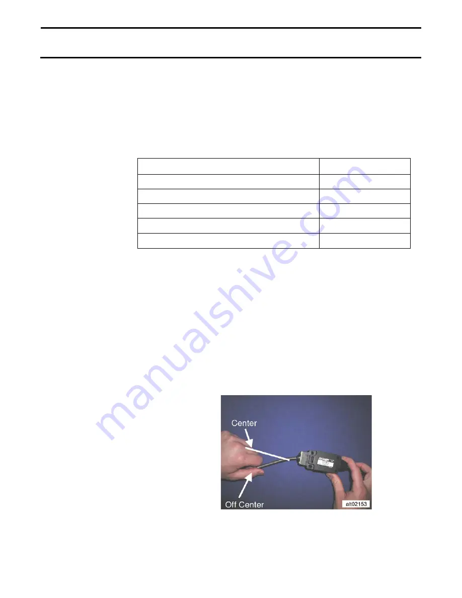
2. The mounting orientation of the implement Switch Assembly
determines whether the lever is off center or centered when the
implement is in the “application” position.
3. For an off center orientation plug the 3-pin Weatherpack Shroud
labeled
NORMALLY OPEN
on the Implement Switch into the 3-pin


