Installation, assembly and setting
Assembly instructions EN
DG 16
Edition 07/2020
Rev. 3.0
31–50
6.2 Preparation - Manufacture of the gripper fingers
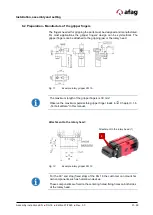
The fingers needed for gripping the parts must be designed and manufactured.
For most applications the gripper fingers’ design can be symmetrical. The
gripper fingers can be attached to the gripping jaw or the rotary head.
Fig. 11
Example rotary gripper DG 16
The maximum length of the gripper fingers is 30 mm!
Observe the maximum permissible gripper finger loads in
Chapter 3.1.6
„Technical Data“ in this manual.
Attachment to the rotary head:
Fig. 12
Example rotary gripper DG 16
For the 90° end stop (fixed stop) of the DG 16 the customer can mount his
own components such as hold-down devices.
These components are fixed to the centering holes/ fixing holes on both sides
of the rotary head.
Attachment to the rotary head (1)
1


