+ User Manual
Plug-in stepper drivers
Before inserting the Pololu or StepStick driver modules in the sockets, the DIP switches should
be set for the proper micro-stepping options. Refer to the stepper-module’s documentation
for the proper settings. The numbers on the switches correspond with the MS input signals of
the modules. The 'on' position of a switch makes the corresponding signal high ('1'), in the 'off'
position the signal is set low ('0').
Take care to orient the modules properly as there are no provisions to prevent improper
orientation. Inserting a module backwards will destroy the module and may damage the
rest of the hardware.
Refer to the photos in this document for the proper orientation.
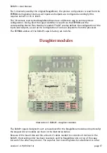
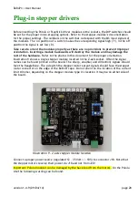
illustration 9 shows a single stepper module inserted in the Z-axis socket. Often the signal
names can be found printed on the board. The st(e)p, ena(ble) and dir(ection) signals should
face the BeagleBone. The side with the stepper motor output signals should face the stepper
motor connector on the edge of the BeBoPr cape. Do not orient on the location of the current
limit trimmer, depending on the stepper module type it's location it may be on either side of
the board.
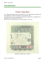
Connect a proper power source (regulated 12 – 35 Volt +/- 10%) to connector J18. Note that
the stepper motors receive their power via J18 and not from J20!
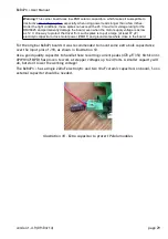
Important: Pololu modules can be damaged by the back-feed from the motors. On the Pololu
site the following warning can be found:
version 1.4.9 (09/04/14)
page 28
Illustration 9 - Z-axis stepper module location


