+ User Manual
+ Features
Although designed as 3D printer controller, the + can be used for many other
applications. This chapter describes the interfaces in a generic way first, followed by
mapping these features on 3D printer hardware.
Generic I/O view
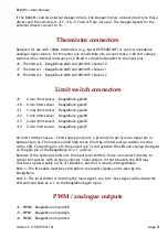
Analogue inputs (3x)
Three analogue inputs accept a 0 - 3.6 Volt input range. The inputs are protected against
over-voltage: Accidental shorts between thermistor wires and the 12 Volt supply voltage will
not destroy the BeagleBone.
The input filter scales (by a factor 0.5) and limits the analogue input signals to the
BeagleBone's 0 - 1.8 Volt range.
Instead of using the troublesome BeagleBone's on-chip ADC, a more stable 12-bit ADS1015 is
present on the +. It operates in parallel to the BeagleBone's ADC and uses a standard
Linux driver.
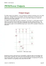
Analogue (PWM) outputs (3x)
Three high power outputs are connected to the processor's PWM devices. These outputs can
also be used as digital outputs, to control a relay, a motor, or other DC load.
Digital inputs (6x)
Six digital inputs can be used for simple logic signals, or to connect switches or opto sensors
directly. The three pin connectors also provide a +5 Volt signal for sensors that need a supply
voltage. The supply is protected against short-circuits by a thermal fuse.
Digital outputs (12x)
5 Volt TTL/CMOS level compatible outputs are available on a header connector.
These outputs can be switched to tristate via software and by an active low disable signal.
Supply
The board can operate from a single power supply that provides a DC voltage in the range
12 to 24 Volts. If required, the stepper drivers can operate from a different supply than that
is used for the board. An efficient step down converter generates the 5 Volt supply for the
BeagleBone. This makes the + compatible with almost any kind of DC power
version 1.4.9 (09/04/14)
page 11


