+ User Manual
Specifications
(preliminary)
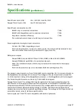
Board Power input (J20):
min. 10.8 Volt, max 26.4 Volt
Stepper Power input (J18):
max 35 Volt (see text)
Board Power consumption via J20:
BeBoPr only, no external connections:
T.B.D.
BeBoPr with BeagleBone and no external connections
T.B.D.
Step-down converter efficiency
T.B.D.
The combined current drawn via J20 may not exceed 16A.
Power supplied to the digital input connectors:
5.0 Volt +5%/-TBD%, depending on load.
Short circuit protection, in case of a short circuit, the current will be reduced to less
than 0.3A within 30 seconds by a thermal (PTC type) fuse (F4).
PWM power outputs:
Output PWM2 (J4) can deliver 10A at 12 Volt (120W) or 8A at 24 Volt (200W).
Outputs PWM0 (J2) and PWM1 (J3) can deliver 4A each.
Note: The combined output currents may not exceed the rated 16A for the supply
connector.
Short circuit protection by a non-resettable 5x20 mm cartridge fuse (F1).
The stepper output signals on J5 are 5 Volt CMOS level compatible. Pin 16 connects directly to
the BeagleBone once jumper JP3 is closed. The voltage on this pin should
never
exceed the
3.3 Volts maximum rating of the BeagleBone's processor, or the BeagleBone
will
be damaged!
The Pololu/StepStick boards are driven by 5 Volt CMOS level signals.
Stepper Power input: The voltage that may be applied on this input is determined by the
specification of the stepper modules and the components on the BeBoPr. The BeBoPr uses
components specified for 50 Volts but because of the voltage peaks that are generated by the
motors the maximum allowed working voltage is 35 Volts. Note that many stepper driver
modules have an even lower maximum operating voltage. The voltage on this input should not
exceed the lowest value of all these specifications.
Sensor inputs are 5 Volt TTL level compatible with built-in hysteresis.
version 1.4.9 (09/04/14)
page 37

