+ User Manual
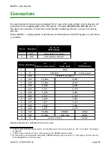
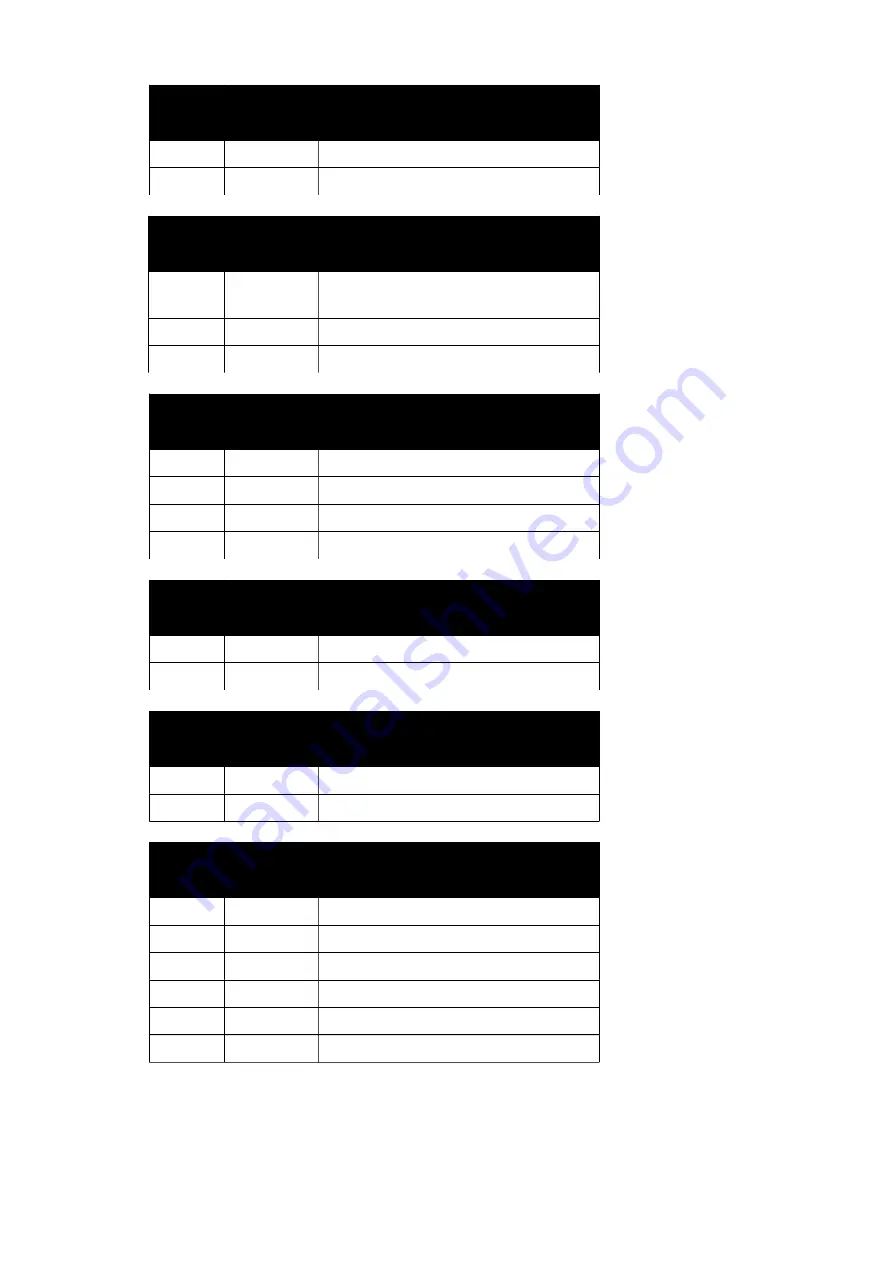
Pin nr
Direction
J6, J7, J8
analogue inputs
1
IN
Positive terminal
2
-
GND - Negative terminal
Pin nr
Direction
J9, J10, J11, J12, J13, J14
digital inputs
1
OUT
+5 Volt supply
(200 mA max over all connectors)
2
IN
Input, switch to GND
3
-
GND
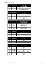
Pin nr
Direction
J15, J16, J17, J19
stepper motors
1
OUT
Stepper coil 1 A
2
OUT
Stepper coil 1 B
3
OUT
Stepper coil 2 A
4
OUT
Stepper coil 2 B
Pin nr
Direction
J18
stepper power input
1
-
GND
2
IN
Positive terminal stepper power
Pin nr
Direction
J20
board power input
1
-
GND
2
IN
Positive terminal input power
Pin nr
Direction
J22
I2C and ESTOP
1
-
GND
2
IN/OUT
SDA
3
IN/OUT
SCL
4
IN
External VCC (3.3 – 5.0 Volt)
5
IN
ESTOP
6
-
GND
version 1.4.9 (09/04/14)
page 39

