


english
foreseen use
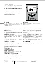
The central power unit was designed to be connected
to tubing able to vacuum dust. The operator uses
the hose and cleaning accessories connected to the
Aertecnica sockets. The system must only be used by a
single operator to only vacuum dust or minuscule solid
particles, using only one vacuum socket at a time in
order to secure adequate efficiency.
The CLEAN bAG (in the PERFETTO TXA, TPA and TP series)
must be replaced with a new one each time that it is
filled.
The dust container (in the CLASSIC TC series) must be
emptied each time that it is filled.
The filter cartridge must be regenerated periodically
and must be replaced every 2-3 years or immediately
if it breaks. When replacing spare parts, use original
Aertecnica spare parts.
prohibiteD use
- Do not vacuum lighted cigarettes, hot embers or
burning material: these materials may cause a fire to
start that would damage the hoses and the central
power unit.
- Do not vacuum cloths, rags, fabrics or textile material:
these materials could obstruct the hoses or damage the
central power unit .
- Do not allow children to play with the vacuum sockets,
opening and closing them continuously or inserting
toys or solid items of unsuitable dimensions.
- Do not use the system with the central power unit
turned on without the filter cartridge inserted.
- Do not block the air exhaust line.
- Do not block the air sockets for electric motor cooling.
- Do not use the cleaning accessories to vacuum parts
of the body.
- Do not install the central power unit in an environment
classified as ATEX as per European Union standards.
unauthoriseD use
- Do not vacuum liquids, materials saturated with
liquids or very moist materials: these materials could
cause the electric system to short circuit, prevent the
proper passage of the dust or damage the sockets and
the central power unit.
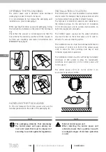
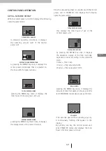
turninG on/off
The standard hose comes in two types:
TYPE 1
: hose with an activator union: the central
power unit turns on when the union (b) is inserted in the
vacuum socket (A).
TYPE 2
: hose with a switch: the central power unit is
turned on using the switch on the hose itself.
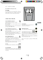
Insert the hose-socket union with the special plates (D)
in correspondence of the contacts (E) inside the socket.
To turn off the central power unit:
with the TYPE 1 hose, remove the hose from the vacuum
socket (A);
with the TYPE 2 hose, move the switch to the OFF position
Liquid can be vacuumed using a special accessory (art.
AP372; art. AP373).
- Do not vacuum dust using more than one vacuum
socket at the same time.
- Never leave the hose and cleaning accessories
connected to the system unattended whilst the central
power unit is on.
operator
The operator must not present limited physical, sensory
or mental capabilities; the operator must not be an
unskilled person or a person with no knowledge of
the product unless the aforementioned is under the
supervision of somebody responsible for their safety or
has received instructions with regards using the central
power unit.
The operator must be over the age of 14 years.
The operator must always be careful when using the
system in order to avoid tripping over the hose or
cleaning accessories connected to the system, and must
extend these same personal safety measures to the
persons which may be present in the area at the same
time.
Use personal protection garments before
carrying out operations such as emptying
the dust container or replacing/cleaning the
filtering cartridge.
E
A
B
E
A
D
C
TYPE 1
TYPE 2
User and maintenance manual
8
General information
General information