BM/BMS Series Hardware Manual
Introduction
www.aerotech.com 1-23
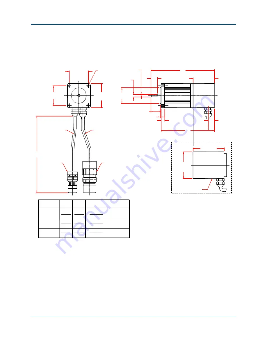
1.8. Brushless Motor Dimensions
The following figures show the outline dimensions of each model in BM series brushless
motors.
Motor
Model No.
A
B
BM75
BM130
4 Holes
6.20"
7.40"
8.60"
BM200
0.2498"
0.3747"
C
0.3747"
Cable, Motor
Cable, Sensors (Feedback)
C
Typ.
7.60"
6.40"
5.20"
MS3101A-20-29P
0.5[0.02]
2 Flats At 90° Apart
157.5
187.9
218.4
193.0
132.1
Ø 6,345
Ø 9,517
Ø 9,517
162.6
**
*
Add 3.2[0.13 IN,] Per Side For Optional Brake.
Brake (Optional)
**
Add 77.2[3.04 IN.] To Length For Optional Brake.
**
MS3101A-18-10P
+0.0000", -0.0005"
+0.000, -0.013
+0.0000", -0.0005"
+0.0000", -0.0005"
+0.000, -0.013
+0.000, -0.013
47.1 [1.86]
47.142 [1.86]
57.2 [2.25]
Ø5.0 [Ø0.20]
Square
38.1 [1.50]
A
16.0 [0.63]
53.1 [2.09]
8.6 [0.34]
2.5 [0.10]
25.4 [1.00]
15.0 [0.59]
B
380[15]
77.3 [3.04]
63.5 [2.50]
*
**
Square
Shaft Dia.
Dimensions - millimeters [inches]
**
**
Figure 1-8:
BM75, BM130, BM200 Model Dimensions (NEMA 23)
Summary of Contents for BM Series
Page 6: ...Table of Contents BM BMS Series Hardware Manual iv www aerotech com...
Page 8: ...List of Figures BM BMS Series Hardware Manual vi www aerotech com...
Page 10: ...List of Tables BM BMS Series Hardware Manual viii www aerotech com...
Page 12: ...Declaration of Conformity BM BMS Series Hardware Manual x www aerotech com...
Page 50: ...Appendix A BM BMS Series Hardware Manual A 8 www aerotech com...
Page 56: ...Index BM BMS Series Hardware Manual Index 2 www aerotech com...
Page 58: ......

