BM/BMS Series Hardware Manual
Introduction
www.aerotech.com 1-25
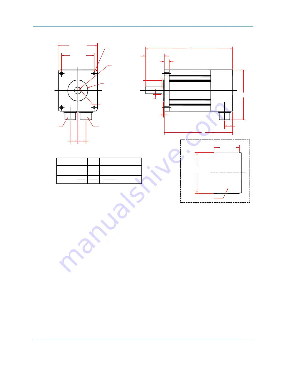
Cable Connector
Motor
MS3102A18-10P
MS3102A20-29P
Cable Connector
Sensor (Feedback)
4.8[0.187] Sq. Keyway
By 38[1.50] Lg.
Ø7.1 [Ø0.28]
Thru 4 Holes
C
Shaft Dia.
Add 68.9[2.71 IN.] To Length For Optional Brake.
*
BM800
BM1400
Motor
Model No.
+0.0000", -0.0005"
+0.0000", -0.0005"
+0.000, -0.013
+0.000, -0.013
238
187
318
12.52"
9.37"
267.2
10.52"
7.37"
A
B
Ø 19.04
Ø 19.04
0.7497"
0.7497"
C
108.0 [4.25]
88.9 [3.50]
20.6 [0.81]
22.2 [0.87]
13.2 [0.52]
50.8 [2.00]
A
44.5 [1.75]
2.4 [0.09]
1.0 [0.04]
B
22.2 [0.87]
130.2 [5.13]
68.9 [2.71]
Square
2 Flats
90° Apart
Typ.
108.0 [4.25]
Square
Brake (Optional)
*
Ø55.6 [Ø2.19]
Square
Dimensions - millimeters [inches]
*
*
*
*
Figure 1-10:
BM800, BM1400 Model Dimensions (NEMA 42)
Summary of Contents for BM Series
Page 6: ...Table of Contents BM BMS Series Hardware Manual iv www aerotech com...
Page 8: ...List of Figures BM BMS Series Hardware Manual vi www aerotech com...
Page 10: ...List of Tables BM BMS Series Hardware Manual viii www aerotech com...
Page 12: ...Declaration of Conformity BM BMS Series Hardware Manual x www aerotech com...
Page 50: ...Appendix A BM BMS Series Hardware Manual A 8 www aerotech com...
Page 56: ...Index BM BMS Series Hardware Manual Index 2 www aerotech com...
Page 58: ......


